link管理
链接快照平台
- 输入网页链接,自动生成快照
- 标签化管理网页链接
相关文章推荐

|
不拘小节的金针菇 · OpenText | Secure ...· 2 月前 · |
|
|
刚分手的茶壶 · Question Thread - Tanzu· 3 周前 · |
|
|
深情的小摩托 · 台北金馬影展 Taipei Golden ...· 4 月前 · |
|
|
玉树临风的黄瓜 · 推行“行业公开课” ...· 6 月前 · |
|
|
另类的砖头 · 《一生的旅程》:罗伯特·艾格领导迪士尼的战略 ...· 1 年前 · |
|
|
爱跑步的松鼠 · android studio导出项目 - ...· 1 年前 · |
|
|
俊逸的创口贴 · Invalid header ...· 1 年前 · |
link管理
›
Networking Guide Red Hat Enterprise Linux 7 | Red Hat Customer Portal
| enterprise |
| https://access.redhat.com/documentation/en-us/red_hat_enterprise_linux/7/html-single/networking_guide/index |

|
冷静的围巾
2 年前 |
Increase visibility into IT operations to detect and resolve technical issues before they impact your business.
Learn More Go to InsightsEngage with our Red Hat Product Security team, access security updates, and ensure your environments are not exposed to any known security vulnerabilities. Product Security Center
Keep your systems secure with Red Hat's specialized responses to security vulnerabilities. View Responses
Ioanna Gkioka
Red Hat
Customer Content Services
Mirek Jahoda
Red Hat
Customer Content Services
Jana Heves
Red Hat
Customer Content Services
Stephen Wadeley
Red Hat
Customer Content Services
Christian Huffman
Red Hat
Customer Content Services
Abstract
The
Red Hat Enterprise Linux 7 Networking Guide
documents relevant information regarding the configuration and administration of network interfaces, networks and network services in Red Hat Enterprise Linux. It is oriented towards system administrators with a basic understanding of Linux and networking.
To expand your expertise, you might also be interested in the
Red Hat System Administration I (RH124)
training course.
Part I. Before You Begin
This documentation part provides an overview of basic concepts of the network services in Red Hat Enterprise Linux.
Chapter 1. Overview of Networking Topics
1.1. Comparing IP to non-IP Networks
Network is a system of interconnected devices that can communicate sharing information and resources, such as files, printers, applications, and Internet connection. Each of these devices has a unique Internet Protocol (IP) address to send and receive messages between two or more devices using a set of rules called protocol.
Categories of Network Communication
- IP Networks
-
Networks that communicate through Internet Protocol addresses. An IP network is implemented in the Internet and most internal networks. Ethernet, Cable Modems, DSL Modems, dial up modems, wireless networks, and VPN connections are typical examples.
- non-IP Networks
-
Networks that are used to communicate through a lower layer rather than the transport layer. Note that these networks are rarely used. InfiniBand is a non-IP network, described in Chapter 13, Configure InfiniBand and RDMA Networks .
1.2. Comparing Static to Dynamic IP Addressing
- Static IP addressing
-
When a device is assigned a static IP address, the address does not change over time unless changed manually. It is recommended to use static
IPaddressing if you want: To ensure network address consistency for servers such asDNS, and authentication servers. To use out-of-band management devices that work independently of other network infrastructure. All the configuration tools listed in Section 3.1, “Selecting Network Configuration Methods” allow assigning staticIPaddresses manually. The nmcli tool is also suitable, described in Section 3.3.8, “Adding and Configuring a Static Ethernet Connection with nmcli” . For more information on automated configuration and management, see the OpenLMI chapter in the Red Hat Enterprise Linux 7 System Administrators Guide . The Red Hat Enterprise Linux 7 Installation Guide documents the use of a Kickstart file which can also be used for automating the assignment of network settings. - Dynamic IP addressing
-
When a device is assigned a dynamic IP address, the address changes over time. For this reason, it is recommended for devices that connect to the network occasionally because IP address might be changed after rebooting the machine. Dynamic IP addresses are more flexible, easier to set up and administer. The dynamic host control protocol ( DHCP ) is a traditional method of dynamically assigning network configurations to hosts. See Section 14.1, “Why Use DHCP?” for more information. You can also use the nmcli tool, described in Section 3.3.7, “Adding and Configuring a Dynamic Ethernet Connection with nmcli” . There is no strict rule defining when to use static or dynamic IP address. It depends on user's needs, preferences and the network environment. By default, NetworkManager calls the
DHCPclient, dhclient .
1.3. Configuring the DHCP Client Behavior
A Dynamic Host Configuration Protocol (DHCP) client requests the dynamic IP address and corresponding configuration information from a DHCP server each time a client connects to the network.
Note that
NetworkManager
calls the
DHCP
client,
dhclient
by default.
Requesting an IP Address
When a
DHCP
connection is started, a dhcp client requests an IP address from a
DHCP
server. The time that a dhcp client waits for this request to be completed is 60 seconds by default. You can configure the
ipv4.dhcp-timeout
property using the
nmcli
tool or the
IPV4_DHCP_TIMEOUT
option in the
        /etc/sysconfig/network-scripts/ifcfg-

         ifname
file. For example, using
nmcli
:
~]# nmcli connection modify enp1s0 ipv4.dhcp-timeout 10
If an address cannot be obtained during this interval, the IPv4 configuration fails. The whole connection may fail, too, and this depends on the
ipv4.may-fail
property:
If
ipv4.may-fail
is set to
yes
(default), the state of the connection depends on IPv6 configuration:
If the IPv6 configuration is enabled and successful, the connection is activated, but the IPv4 configuration can never be retried again.
If the IPv6 configuration is disabled or does not get configured, the connection fails.
If
ipv4.may-fail
is set to
no
the connection is deactivated. In this case:
If the
autoconnect
property of the connection is enabled,
NetworkManager
retries to activate the connection as many times as set in the
autoconnect-retries
property. The default is 4.
If the connection still cannot acquire the dhcp address, auto-activation fails.
Note that after 5 minutes, the auto-connection process starts again and the dhcp client retries to acquire an address from the dhcp server.
Requesting a Lease Renewal
When a dhcp address is acquired and the IP address lease cannot be renewed, the dhcp client is restarted for three times every 2 minutes to try to get a lease from the dhcp server. Each time, it is configured by setting the
ipv4.dhcp-timeout
property in seconds (default is 60) to get the lease. If you get a reply during your attempts, the process stops and you get your lease renewed.
After three attempts failed:
If
ipv4.may-fail
is set to
yes
(default) and IPv6 is successfully configured, the connection is activated and the dhcp client is restarted again every 2 minutes.
If
ipv4.may-fail
is set to
no
, the connection is deactivated. In this case, if the connection has the
autoconnect
property enabled, the connection is activated from scratch.
1.3.1. Making DHCPv4 Persistent
To make DHCPv4 persistent both at startup and during the lease renewal processes, set the
ipv4.dhcp-timeout
property either to the maximum for a 32-bit integer (MAXINT32), which is
2147483647
, or to the
infinity
value:
~]$ nmcli connection modify enps1s0 ipv4.dhcp-timeout infinity
As a result,
NetworkManager
never stops trying to get or renew a lease from a DHCP server until it is successful.
To ensure a DHCP persistent behavior only during the lease renewal process, you can manually add a static IP to the
IPADDR
property in the
      /etc/sysconfig/network-scripts/ifcfg-

       enp1s0
configuration file or by using
nmcli
:
~]$ nmcli connection modify enp1s0 ipv4.address 192.168.122.88/24
When an IP address lease expires, the static IP preserves the IP state as configured or partially configured (you can have an IP address, but you are not connected to the Internet), making sure that the dhcp client is restarted every 2 minutes.
1.4. Setting the Wireless Regulatory Domain
In Red Hat Enterprise Linux, the
crda
package contains the Central Regulatory Domain Agent that provides the kernel with the wireless regulatory rules for a given jurisdiction. It is used by certain
udev
scripts and should not be run manually unless debugging
udev
scripts. The kernel runs
crda
by sending a
udev
event upon a new regulatory domain change. Regulatory domain changes are triggered by the Linux wireless subsystem (IEEE-802.11). This subsystem uses the
regulatory.bin
file to keep its regulatory database information.
The
setregdomain
utility sets the regulatory domain for your system.
Setregdomain
takes no arguments and is usually called through system script such as
udev
rather than manually by the administrator. If a country code look-up fails, the system administrator can define the
COUNTRY
environment variable in the
/etc/sysconfig/regdomain
file.
See the following man pages for more information about the regulatory domain:
setregdomain(1)
man page — Sets regulatory domain based on country code.
crda(8)
man page — Sends to the kernel a wireless regulatory domain for a given ISO or IEC 3166 alpha2.
regulatory.bin(5)
man page — Shows the Linux wireless regulatory database.
iw(8)
man page — Shows or manipulates wireless devices and their configuration.
1.5. Configuring
netconsole
If disk logging fails or using the serial console is not possible, you might need to use kernel debugging. The
netconsole
kernel module enables to log kernel messages to another computer over the network.
To be able to use
netconsole
, you need to have an
rsyslog
server that is properly configured on your network.
Procedure 1.1. Configuring an rsyslog server for netconsole
-
Configure the
rsyslogddaemon to listen on the 514/udp port and receive messages from the network by uncommenting the following lines in theMODULESsection of the/etc/rsyslog.conffile:$ModLoad imudp $UDPServerRun 514
Restart thersyslogdservice for the changes to take effect:]#
Verify thatsystemctl restart rsyslogrsyslogdis listening on the 514/udp port:]#
Thenetstat -l | grep syslogudp 0 0 0.0.0.0:syslog 0.0.0.0:* udp6 0 0 [::]:syslog [::]:*0.0.0.0:syslogand[::]:syslogvalues in thenetstat -loutput mean thatrsyslogdis listening on defaultnetconsoleport defined in the/etc/servicesfile:]$
cat /etc/services | grep syslogsyslog 514/udp syslog-conn 601/tcp # Reliable Syslog Service syslog-conn 601/udp # Reliable Syslog Service syslog-tls 6514/tcp # Syslog over TLS syslog-tls 6514/udp # Syslog over TLS syslog-tls 6514/dccp # Syslog over TLSNetconsoleis configured using the/etc/sysconfig/netconsolefile, which is a part of the initscripts package. This package is installed by default and it also provides thenetconsoleservice. If you want to configure a sending machine, follow this procedure:Procedure 1.2. Configuring a Sending Machine
-
Set the value of the
SYSLOGADDRvariable in the/etc/sysconfig/netconsolefile to match the IP address of thesyslogdserver. For example:SYSLOGADDR=192.168.0.1
Restart thenetconsoleservice for the changes to take effect:]#
Enablesystemctl restart netconsole.servicenetconsole.serviceto run after rebooting the system:]#
View thesystemctl enable netconsole.servicenetconsolemessages from the client in the/var/log/messagesfile (default) or in the file specified inrsyslog.conf.]#
By default,cat /var/log/messagesrsyslogdandnetconsole.serviceuse port 514. To use a different port, change the following line in/etc/rsyslog.confto the required port number:$UDPServerRun <PORT>
On the sending machine, uncomment and edit the following line in the/etc/sysconfig/netconsolefile:SYSLOGPORT=514
-
For more information about
netconsole
configuration and troubleshooting tips, see
Netconsole Kernel Documentation
.
1.6. Using Network Kernel Tunables with sysctl
Using certain kernel tunables through the
sysctl
utility, you can adjust network configuration on a running system and directly affect the networking performance.
To change network settings, use the
sysctl
commands. For permanent changes that persist across system restarts, add lines to the
/etc/sysctl.conf
file.
To display a list of all available
sysctl
parameters, enter as
root
:
~]# sysctl -a
For more details on network kernel tunables using
sysctl
, see the
Using PTP with Multiple Interfaces
section in the System Administrator's Guide.
For more information on network kernel tunables, see the
Network Interface Tunables
section in the Kernel Administration Guide.
1.7. Managing Data Using the ncat utility
The
ncat
networking utility replaces
netcat
in Red Hat Enterprise Linux 7.
ncat
is a reliable back-end tool that provides network connectivity to other applications and users. It reads and writes data across the network from the command line, and uses Transmission Control Protocol (TCP), User Datagram Protocol (UDP), Stream Control Transmission Protocol (SCTP) or Unix sockets for communication.
ncat
can deal with both
IPv4
and
IPv6
, open connections, send packets, perform port scanning, and supports higher-level features such as
SSL
, and connection broker.
The
nc
command can also be entered as
ncat
, using the identical options. For more information about the
ncat
options, see
the New networking utility (ncat) section in the Migration Planning Guide
and the
ncat
(1)
man page.
Installing ncat
To install the
ncat
package, enter as
root
:
~]# yum install ncat
Brief Selection of ncat Use Cases
Example 1.1. Enabling Communication between a Client and a Server
-
Set a client machine to listen for connections on TCP port 8080 :
~]$
On a server machine, specify the IP address of the client and use the same port number:ncat -l 8080~]$
You can send messages on either side of the connection and they appear on both local and remote machines. Pressncat 10.0.11.60 8080Ctrl+Dto close the TCP connection. To check a UDP port, use the samenccommands with the–uoption. For example:~]$
ncat -u -l 8080
Example 1.2. Sending Files
Instead of printing information on the screen, as mentioned in the previous example, you can send all information to a file. For example, to send a file over TCP port
8080
from a client to a server:
On a client machine, to listen a specific port transferring a file to the server machine:
~]$ ncat -l 8080 > outputfile
On a server machine, specify the IP address of the client, the port and the file which is to be transferred:
~]$ ncat -l 10.0.11.60 8080 < inputfile
After the file is transferred, the connection closes automatically.
You can transfer a file in the other direction as well:
~]$ ncat -l 8080 < inputfile
~]$ ncat -l 10.0.11.60 8080 > outputfile
Example 1.3. Creating an HTTP proxy server
To create an HTTP proxy server on localhost port
8080
:
~]$ ncat -l --proxy-type http localhost 8080
Example 1.4. Port Scanning
To view which ports are open, use the
–z
option and specify a range of ports to scan:
~]$  ncat -z 10.0.11.60 80-90
    Connection to 192.168.0.1 80 port [tcp/http] succeeded!
Example 1.5. Setting up Secure Client-Server Communication Using SSL
Set up
SSL
on a server:
~]$ ncat -e /bin/bash -k -l 8080 --ssl
On a client machine:
~]$ ncat --ssl 10.0.11.60 8080
To ensure true confidentiality of the
SSL
connection, the server requires the
--ssl-cert
and
--ssl-key
options, and the client requires the
--ssl-verify
and
--ssl-trustfile
options. For information on
OpenSSL
, see the
Using OpenSSL section in the Security Guide
.
For more examples, see the
ncat
(1)
man page.
Part II. Managing IP Networking
This documentation part provides detailed instruction on how to configure and manage networking in Red Hat Enterprise Linux.
Chapter 2. Getting Started with NetworkManager
2.1. Overview of NetworkManager
In Red Hat Enterprise Linux 7, the default networking service is provided by
NetworkManager
, which is a dynamic network control and configuration daemon to keep network devices and connections up and active when they are available. The traditional
ifcfg
type configuration files are still supported. See
Section 2.6, “Using NetworkManager with Network Scripts”
for more information.
2.1.1. Benefits of Using NetworkManager
The main benefits of using NetworkManager are:
Making Network management easier:
NetworkManager
ensures that network connectivity works. When it detects that there is no network configuration in a system but there are network devices,
NetworkManager
creates temporary connections to provide connectivity.
Providing easy setup of connection to the user:
NetworkManager
offers management through different tools —
GUI, nmtui, nmcli
—. See
Section 2.5, “NetworkManager Tools”
.
Supporting configuration flexibility. For example, configuring a WiFi interface,
NetworkManager
scans and shows the available wifi networks. You can select an interface, and
NetworkManager
displays the required credentials providing automatic connection after the reboot process.
NetworkManager
can configure network aliases, IP addresses, static routes, DNS information, and VPN connections, as well as many connection-specific parameters. You can modify the configuration options to reflect your needs.
Offering an API through D-Bus which allows applications to query and control network configuration and state. In this way, applications can check or configure networking through D-BUS. For example, the
web console
interface, which monitors and configures servers through a web browser, uses the
NetworkManager
D-BUS interface to configure networking.
Maintaining the state of devices after the reboot process and taking over interfaces which are set into managed mode during restart.
Handling devices which are not explicitly set unmanaged but controlled manually by the user or another network service.
2.2. Installing NetworkManager
NetworkManager
is installed by default on Red Hat Enterprise Linux. If it is not, enter as
root
:
~]# yum install NetworkManager
For information on user privileges and gaining privileges, see the
Red Hat Enterprise Linux System Administrator's Guide
.
2.3. Checking the Status of NetworkManager
To check whether
NetworkManager
is running:
~]$ systemctl status NetworkManager
NetworkManager.service - Network Manager
   Loaded: loaded (/lib/systemd/system/NetworkManager.service; enabled)
   Active: active (running) since Fri, 08 Mar 2013 12:50:04 +0100; 3 days ago
Note that the
systemctl status
command displays
Active: inactive (dead)
when
NetworkManager
is not running.
2.4. Starting NetworkManager
To start
NetworkManager
:
~]# systemctl start NetworkManager
To enable
NetworkManager
automatically at boot time:
~]# systemctl enable NetworkManager
For more information on starting, stopping and managing services, see the
Red Hat Enterprise Linux System Administrator's Guide
.
2.5. NetworkManager Tools
Table 2.1. A Summary of NetworkManager Tools and Applications
| Application or Tool | Description |
|---|---|
| nmcli | A command-line tool which enables users and scripts to interact with NetworkManager . Note that nmcli can be used on systems without a GUI such as servers to control all aspects of NetworkManager . It has the same functionality as GUI tools. |
| nmtui | A simple curses-based text user interface (TUI) for NetworkManager |
| nm-connection-editor |
A graphical user interface tool for certain tasks not yet handled by the
control-center
utility such as configuring bonds and teaming connections. You can add, remove, and modify network connections stored by
NetworkManager
. To start it, enter
nm-connection-editor
in a terminal:
~]$ nm-connection-editor
|
| control-center | A graphical user interface tool provided by the GNOME Shell, available for desktop users. It incorporates a Network settings tool. To start it, press the Super key to enter the Activities Overview, type Network and then press Enter . The Network settings tool appears. |
| network connection icon | A graphical user interface tool provided by the GNOME Shell representing network connection states as reported by NetworkManager . The icon has multiple states that serve as visual indicators for the type of connection you are currently using. |
2.6. Using NetworkManager with Network Scripts
This section describes how to run a script and how to use custom commands in network scripts.
The term
network scripts
refers to the script
/etc/init.d/network
and any other installed scripts it calls. Although
NetworkManager
provides the default networking service, scripts and
NetworkManager
can run in parallel and work together. Red Hat recommends to test them first.
Running Network Script
Run a network script
only
with the
systemctl
command:
systemctl start|stop|restart|status network
/etc/init.d/network
checks with
NetworkManager
to avoid tampering with
NetworkManager
's connections.
NetworkManager
is intended to be the primary application using sysconfig configuration files, and
/etc/init.d/network
is intended to be secondary.
The
/etc/init.d/network
script runs:
manually - using one of the
systemctl
commands
        start|stop|restart

       network
,
on boot and shutdown if the network service is enabled - as a result of the
systemctl enable network
command.
It is a manual process and does not react to events that happen after boot. Users can also call the
ifup
and
ifdown
scripts manually.
The
systemctl reload network.service
command does not work due to technical limitations of initscripts. To apply a new configuration for the network service, use the
restart
command:
~]# systemctl restart network.service
This brings down and brings up all the Network Interface Cards (NICs) to load the new configuration. For more information, see the Red Hat Knowledgebase solution
Reload and force-reload options for network service
.
Using Custom Commands in Network Scripts
Custom commands in the
/sbin/ifup-local
,
ifdown-pre-local
, and
ifdown-local
scripts are only executed if these devices are controlled by the
/etc/init.d/network
service. The
ifup-local
file does not exist by default. If required, create it under the
/sbin/
directory.
The
ifup-local
script is readable only by the initscripts and not by
NetworkManager
. To run a custom script using
NetworkManager
, create it under the
dispatcher.d/
directory. See
the section called “Running Dispatcher scripts”
.
Important
Modifying any files included with the initscripts package or related
rpms
is not recommended. If a user modifies such files, Red Hat does not provide support.
Custom tasks can run when network connections go up and down, both with the old
network scripts
and with
NetworkManager
. If
NetworkManager
is enabled, the
ifup
and
ifdown
script will ask
NetworkManager
whether
NetworkManager
manages the interface in question, which is found from the
“
DEVICE=
”
line in the
ifcfg
file.
Devices managed by
NetworkManager
:
- calling ifup
-
When you call
ifupand the device is managed by NetworkManager , there are two options: If the device is not already connected, thenifupasks NetworkManager to start the connection. If the device is already connected, then nothing to do. - calling ifdown
-
When you call
ifdownand the device is managed by NetworkManager :ifdownasks NetworkManager to terminate the connection. Devices unmanaged by NetworkManager : If you call eitherifuporifdown, the script starts the connection using the older, non-NetworkManager mechanism that it has used since the time before NetworkManager existed.Running Dispatcher scripts
NetworkManager provides a way to run additional custom scripts to start or stop services based on the connection status. By default, the/etc/NetworkManager/dispatcher.d/directory exists and NetworkManager runs scripts there, in alphabetical order. Each script must be an executable file owned byrootand must havewrite permissiononly for the file owner. For more information about running NetworkManager dispatcher scripts, see the Red Hat Knowledgebase solution How to write a NetworkManager dispatcher script to apply ethtool commands .
2.7. Using NetworkManager with sysconfig files
The
/etc/sysconfig/
directory is a location for configuration files and scripts. Most network configuration information is stored there, with the exception of VPN, mobile broadband and PPPoE configuration, which are stored in the
/etc/NetworkManager/
subdirectories. For example, interface-specific information is stored in the
ifcfg
files in the
/etc/sysconfig/network-scripts/
directory.
For global settings, use the
/etc/sysconfig/network
file. Information for VPNs, mobile broadband and PPPoE connections is stored in
/etc/NetworkManager/system-connections/
.
In Red Hat Enterprise Linux 7 if you edit an
ifcfg
file,
NetworkManager
is not automatically aware of the change and has to be prompted to notice the change. If you use one of the tools to update
NetworkManager
profile settings,
NetworkManager
does not implement those changes until you reconnect using that profile. For example, if configuration files have been changed using an editor,
NetworkManager
must read the configuration files again.
To ensure this, enter as
root
to reload all connection profiles:
~]# nmcli connection reload
Alternatively, to reload
only one
changed file,
          ifcfg-

           ifname
:
~]# nmcli con load /etc/sysconfig/network-scripts/ifcfg-ifname
Note that you can specify multiple file names using the above command.
Changes made using tools such as
nmcli
do not require a reload but do require the associated interface to be put down and then up again:
~]# nmcli dev disconnect interface-name
~]# nmcli con up interface-name
For more details about
nmcli
, see
Section 3.3, “Configuring IP Networking with nmcli”
.
NetworkManager
does not trigger any of the network scripts, though the network scripts attempt to trigger
NetworkManager
if it is running when the
ifup
commands are used. See
Section 2.6, “Using NetworkManager with Network Scripts”
for the explanation of the network scripts.
The
ifup
script is a generic script which does a few things and then calls interface-specific scripts such as
          ifup-

           device_name
,
ifup-wireless
,
ifup-ppp
, and so on. When a user runs
ifup enp1s0
manually:
ifup
looks for a file called
/etc/sysconfig/network-scripts/ifcfg-enp1s0
;
if the
ifcfg
file exists,
ifup
looks for the
TYPE
key in that file to determine which type-specific script to call;
ifup
calls
ifup-wireless
or
          ifup-

           device_name
based on
TYPE
;
the type-specific scripts do type-specific setup;
the type-specific scripts let common functions perform
IP
-related tasks like
DHCP
or static setup.
On bootup,
/etc/init.d/network
reads through all the
ifcfg
files and for each one that has
ONBOOT=yes
, it checks whether
NetworkManager
is already starting the DEVICE from that
ifcfg
file. If
NetworkManager
is starting that device or has already started it, nothing more is done for that file, and the next
ONBOOT=yes
file is checked. If
NetworkManager
is not yet starting that device, the initscripts continue with their traditional behavior and call
ifup
for that
ifcfg
file.
The result is that any
ifcfg
file that has
ONBOOT=yes
is expected to be started on system bootup, either by
NetworkManager
or by the initscripts. This ensures that some legacy network types which
NetworkManager
does not handle (such as ISDN or analog dial-up modems) as well as any new application not yet supported by
NetworkManager
are still correctly started by the initscripts even though
NetworkManager
is unable to handle them.
Important
It is recommended to not store the backup files anywhere within the
/etc
directory, or in the same location as the live files, because the script literally does
ifcfg-*
. Only these extensions are excluded:
.old
,
.orig
,
.rpmnew
,
.rpmorig
, and
.rpmsave
.
For more information on using sysconfig files, see
Section 3.5, “Configuring IP Networking with ifcfg Files”
and the
ifcfg
(8)
man page.
2.8. Additional Resources
-
man(1)man page — Describes man pages and how to find them.NetworkManager(8)man page — Describes the network management daemon.NetworkManager.conf(5)man page — Describes theNetworkManagerconfiguration file./usr/share/doc/initscripts- version /sysconfig.txt— Describesifcfgconfiguration files and their directives as understood by the legacy network service./usr/share/doc/initscripts- version /examples/networking/— A directory containing example configuration files.ifcfg(8)man page — Describes briefly theifcfgcommand.
Chapter 3. Configuring IP Networking
As a system administrator, you can configure a network interface either using
NetworkManager
or not.
3.1. Selecting Network Configuration Methods
-
To configure a network interface using NetworkManager , use one of the following tools: the text user interface tool, nmtui . For more details, see Section 3.2, “Configuring IP Networking with nmtui” . the command-line tool, nmcli . For more details, see Section 3.3, “Configuring IP Networking with nmcli” . the graphical user interface tools, GNOME GUI . For more details, see Section 3.4, “ Configuring IP Networking with GNOME GUI ” . To configure a network interface without using NetworkManager : edit the
ifcfgfiles manually. For more details, see Section 3.5, “Configuring IP Networking with ifcfg Files” . use theipcommands. This can be used to assign IP addresses to an interface, but changes are not persistent across reboots; when you reboot, you will lose any changes. For more details, see Section 3.6, “Configuring IP Networking with ip Commands” . To configure the network settings when the root filesystem is not local: use the kernel command-line. For more details, see Section 3.7, “Configuring IP Networking from the Kernel Command line” .
3.2. Configuring IP Networking with nmtui
As a system administrator, you can configure a network interface using the NetworkManager's tool,
nmtui
. See
Section 2.5, “NetworkManager Tools”
.
This procedure describes how to configure networking using the text user interface tool,
nmtui
.
Prerequisites
The
nmtui
tool is used in a terminal window. It is contained in the
NetworkManager-tui
package, but it is not installed along with
NetworkManager
by default. To install
NetworkManager-tui
:
~]# yum install NetworkManager-tui
To verify that
NetworkManager
is running, see
Section 2.3, “Checking the Status of NetworkManager”
.
Procedure
Start the
nmtui
tool:
~]$ nmtui
The text user interface appears.
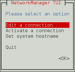
Figure 3.1. The NetworkManager Text User Interface starting menu
To navigate, use the arrow keys or press
Tab
to step forwards and press
Shift
+
Tab
to step back through the options. Press
Enter
to select an option. The
Space
bar toggles the status of a check box.
To apply changes after a modified connection which is already active requires a reactivation of the connection. In this case, follow the procedure below:
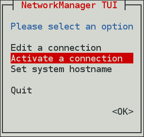 Select the modified connection. On the right, click the
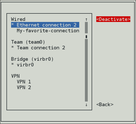 Choose the connection again and click the
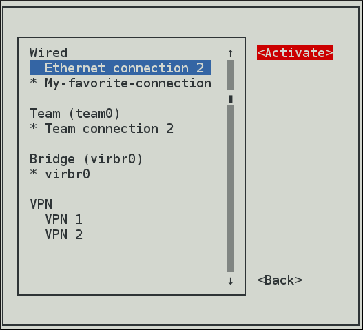 The following commands are also available:
Procedure
Select the
Activate a connection
menu entry.
Figure 3.2. Activate a Connection
Deactivate
button.
Figure 3.3. Deactivate the Modified Connection
Activate
button.
Figure 3.4. Reactivate the Modified Connection
nmtui edit connection-namenmtui connect connection-name
802.1X
.
3.3. Configuring IP Networking with nmcli
The
nmcli
(NetworkManager Command Line Interface) command-line utility is used for controlling NetworkManager and reporting network status. It can be utilized as a replacement for
nm-applet
or other graphical clients. See
Section 2.5, “NetworkManager Tools”
.
nmcli
is used to create, display, edit, delete, activate, and deactivate network connections, as well as control and display network device status.
The
nmcli
utility can be used by both users and scripts for controlling
NetworkManager
:
For servers, headless machines, and terminals,
nmcli
can be used to control
NetworkManager
directly, without GUI, including creating, editing, starting and stopping network connections and viewing network status.
For scripts,
nmcli
supports a terse output format which is better suited for script processing. It is a way to integrate network configuration instead of managing network connections manually.
The basic format of a
nmcli
command is as follows:
nmcli [OPTIONS] OBJECT { COMMAND | help }
where OBJECT can be one of the following options:
general
,
networking
,
radio
,
connection
,
device
,
agent
, and
monitor
. You can use any prefix of these options in your commands. For example,
nmcli con help
,
nmcli c help
,
nmcli connection help
generate the same output.
Some of useful optional OPTIONS to get started are:
- -t, terse
-
This mode can be used for computer script processing as you can see a terse output displaying only the values.
Example 3.1. Viewing a terse output
nmcli -t deviceens3:ethernet:connected:Profile 1 lo:loopback:unmanaged: - -f, field
-
This option specifies what fields can be displayed in output. For example, NAME,UUID,TYPE,AUTOCONNECT,ACTIVE,DEVICE,STATE. You can use one or more fields. If you want to use more, do not use space after comma to separate the fields.
Example 3.2. Specifying Fields in the output
~]$
or even better for scripting:nmcli -f DEVICE,TYPE deviceDEVICE TYPE ens3 ethernet lo loopback~]$
nmcli -t -f DEVICE,TYPE deviceens3:ethernet lo:loopback - -p, pretty
-
This option causes nmcli to produce human-readable output. For example, values are aligned and headers are printed.
Example 3.3. Viewing an output in pretty mode
nmcli -p device===================== Status of devices ===================== DEVICE TYPE STATE CONNECTION -------------------------------------------------------------- ens3 ethernet connected Profile 1 lo loopback unmanaged -- - -h, help
-
Prints help information. The nmcli tool has some built-in context-sensitive help:
-
nmcli help -
This command lists the available options and object names to be used in subsequent commands.
-
nmcli object help -
This command displays the list of available actions related to a specified object. For example,
nmcli c help
3.3.1. Brief Selection of nmcli Examples
Example 3.4. Checking the overall status of NetworkManager
~]$
In terse mode:nmcli general statusSTATE CONNECTIVITY WIFI-HW WIFI WWAN-HW WWAN connected full enabled enabled enabled enabled~]$
nmcli -t -f STATE generalconnectedExample 3.5. Viewing NetworkManager logging status
~]$
nmcli general loggingLEVEL DOMAINS INFO PLATFORM,RFKILL,ETHER,WIFI,BT,MB,DHCP4,DHCP6,PPP,WIFI_SCAN,IP4,IP6,A UTOIP4,DNS,VPN,SHARING,SUPPLICANT,AGENTS,SETTINGS,SUSPEND,CORE,DEVICE,OLPC, WIMAX,INFINIBAND,FIREWALL,ADSL,BOND,VLAN,BRIDGE,DBUS_PROPS,TEAM,CONCHECK,DC B,DISPATCHExample 3.6. Viewing all connections
~]$
nmcli connection showNAME UUID TYPE DEVICE Profile 1 db1060e9-c164-476f-b2b5-caec62dc1b05 ethernet ens3 ens3 aaf6eb56-73e5-4746-9037-eed42caa8a65 ethernet --Example 3.7. Viewing only currently active connections
~]$
nmcli connection show --activeNAME UUID TYPE DEVICE Profile 1 db1060e9-c164-476f-b2b5-caec62dc1b05 ethernet ens3Example 3.8. Viewing only devices recognized by NetworkManager and their state
~]$
You can also use the following abbreviations of the nmcli commands:nmcli device statusDEVICE TYPE STATE CONNECTION ens3 ethernet connected Profile 1 lo loopback unmanaged --Table 3.1. Abbreviations of some nmcli commands
nmcli command abbreviation nmcli general status nmcli g nmcli general logging nmcli g log nmcli connection show nmcli con show nmcli connection show --active nmcli con show -a nmcli device status nmcli dev For more examples, see the nmcli-examples (5) man page.3.3.2. Starting and Stopping a Network Interface Using nmcli
The nmcli tool can be used to start and stop any network interface, including controllers. For example:nmcli con up id bond0 nmcli con up id port0 nmcli dev disconnect bond0 nmcli dev disconnect ens3
Thenmcli connection downcommand, deactivates a connection from a device without preventing the device from further auto-activation. Thenmcli device disconnectcommand, disconnects a device and prevent the device from automatically activating further connections without manual intervention.3.3.3. Understanding the nmcli Options
Following are some of the important nmcli property options. See the comprehensive list in the nmcli (1) man page :-
connection.type -
A connection type. Allowed values are: adsl, bond, bond-slave, bridge, bridge-slave, bluetooth, cdma, ethernet, gsm, infiniband, olpc-mesh, team, team-slave, vlan, wifi, wimax. Each connection type has type-specific command options. You can see the
TYPE_SPECIFIC_OPTIONSlist in the nmcli (1) man page. For example: Agsmconnection requires the access point name specified in anapn.nmcli c add connection.type gsm apn access_point_name
Awifidevice requires the service set identifier specified in assid.nmcli c add connection.type wifi ssid My identifier
-
connection.interface-name -
A device name relevant for the connection.
nmcli con add connection.interface-name enp1s0 type ethernet
-
connection.id -
A name used for the connection profile. If you do not specify a connection name, one will be generated as follows:
connection.type -connection.interface-name
Theconnection.idis the name of a connection profile and should not be confused with the interface name which denotes a device (wlp61s0,ens3,em1). However, users can name the connections after interfaces, but they are not the same thing. There can be multiple connection profiles available for a device. This is particularly useful for mobile devices or when switching a network cable back and forth between different devices. Rather than edit the configuration, create different profiles and apply them to the interface as needed. Theidoption also refers to the connection profile name. The most important options for nmcli commands such asshow,up,downare: An identification string assigned by the user to a connection profile. Id can be used in nmcli connection commands to identify a connection. The NAME field in the command output always denotes the connection id. It refers to the same connection profile name that the con-name does. A unique identification string assigned by the system to a connection profile. Theuuidcan be used innmcli connectioncommands to identify a connection.
3.3.4. Using the nmcli Interactive Connection Editor
The nmcli tool has an interactive connection editor. To use it:~]$
You will be prompted to enter a valid connection type from the list displayed. After entering a connection type you will be placed at the nmcli prompt. If you are familiar with the connection types you can add a valid connectionnmcli con edittypeoption to thenmcli con editcommand and be taken straight to the nmcli prompt. The format is as follows for editing an existing connection profile:nmcli con edit [id | uuid | path] ID
For editing a new connection profile:nmcli con edit [type new-connection-type] [con-name new-connection-name]
Typehelpat the nmcli prompt to see a list of valid commands. Use thedescribecommand to get a description of settings and their properties:describe setting.property
For example:nmcli>
describe team.config3.3.5. Creating and Modifying a Connection Profile with nmcli
A connection profile contains the connection property information needed to connect to a data source. To create a new profile for NetworkManager using nmcli :nmcli c add {ARGUMENTS}Thenmcli c addaccepts two different types of parameters:- Property names
-
the names which NetworkManager uses to describe the connection internally. The most important are: connection.type
nmcli c add connection.type
connection.interface-namebondnmcli c add connection.interface-name
connection.idenp1s0nmcli c add connection.id
See the"My Connection"nm-settings(5)man page for more information on properties and their settings. - Aliases names
-
the human-readable names which are translated to properties internally. The most common are: type (the connection.type property)
nmcli c add type
ifname (the connection.interface-name property)bondnmcli c add ifname
con-name (the connection.id property)enp1s0nmcli c add con-name
In previous versions of"My Connection"nmcli, to create a connection required using thealiases. For example,ifnameenp1s0 andcon-nameMy Connection. A command in the following format could be used:nmcli c add type ethernet ifname enp1s0 con-name "My Connection"
In more recent versions, both theproperty namesand thealiasescan be used interchangeably. The following examples are all valid and equivalent:nmcli c add type ethernet ifname enp1s0 con-name "My Connection" ethernet.mtu 1600
nmcli c add connection.type ethernet ifname enp1s0 con-name "My Connection" ethernet.mtu 1600
nmcli c add connection.type ethernet connection.interface-name enps1s0 connection.id "My Connection" ethernet.mtu 1600
The arguments differ according to the connection types. Only thetypeargument is mandatory for all connection types andifnameis mandatory for all types exceptbond,team,bridgeandvlan.- type type_name
-
connection type. For example:
nmcli c add type
bond - ifname interface_name
-
interface to bind the connection to. For example:
nmcli c add ifname interface_name type ethernetTo modify one or more properties of a connection profile, use the following command:
For example, to change thenmcli c modifyconnection.idfrom My Connection toMy favorite connectionand theconnection.interface-nametoenp1s0, issue the command as follows:nmcli c modify "My Connection" connection.id "My favorite connection" connection.interface-name enp1s0
It is preferable to use theproperty names. Thealiasesare used only for compatibility reasons. In addition, to set the ethernet MTU to 1600, modify the size as follows:nmcli c modify "My favorite connection" ethernet.mtu 1600
To apply changes after a modified connection using nmcli, activate again the connection by entering this command:
For example:nmcli con up con-namenmcli con up My-favorite-connectionConnection successfully activated (D-Bus active path: /org/freedesktop/NetworkManager/ActiveConnection/16)
3.3.6. Connecting to a Network Using nmcli
To list the currently available network connections:~]$
Note that thenmcli con showNAME UUID TYPE DEVICE Auto Ethernet 9b7f2511-5432-40ae-b091-af2457dfd988 802-3-ethernet -- ens3 fb157a65-ad32-47ed-858c-102a48e064a2 802-3-ethernet ens3 MyWiFi 91451385-4eb8-4080-8b82-720aab8328dd 802-11-wireless wlp61s0NAMEfield in the output always denotes the connection ID (name). It is not the interface name even though it might look the same. In the second connection shown above,ens3in the NAME field is the connection ID given by the user to the profile applied to the interface ens3 . In the last connection shown, the user has assigned the connection IDMyWiFito the interface wlp61s0 . Adding an Ethernet connection means creating a configuration profile which is then assigned to a device. Before creating a new profile, review the available devices as follows:~]$
nmcli device statusDEVICE TYPE STATE CONNECTION ens3 ethernet disconnected -- ens9 ethernet disconnected -- lo loopback unmanaged --3.3.7. Adding and Configuring a Dynamic Ethernet Connection with nmcli
Adding a Dynamic Ethernet Connection
To add an Ethernet configuration profile with dynamicIPconfiguration, allowingDHCPto assign the network configuration:nmcli connection add type ethernet con-name connection-name ifname interface-name
For example, to create a dynamic connection profile named my-office :~]$
To open the Ethernet connection:nmcli con add type ethernet con-name my-office ifname ens3Connection 'my-office' (fb157a65-ad32-47ed-858c-102a48e064a2) successfully added.~]$
Review the status of the devices and connections:nmcli con up my-officeConnection successfully activated (D-Bus active path: /org/freedesktop/NetworkManager/ActiveConnection/5)~]$
nmcli device statusDEVICE TYPE STATE CONNECTION ens3 ethernet connected my-office ens9 ethernet disconnected -- lo loopback unmanaged --Configuring a Dynamic Ethernet Connection
To change the host name sent by a host to aDHCPserver, modify thedhcp-hostnameproperty:~]$
To change thenmcli con modify my-office my-office ipv4.dhcp-hostname host-name ipv6.dhcp-hostname host-nameIPv4client ID sent by a host to aDHCPserver, modify thedhcp-client-idproperty:~]$
There is nonmcli con modify my-office my-office ipv4.dhcp-client-id client-ID-stringdhcp-client-idproperty forIPv6, dhclient creates an identifier forIPv6. See thedhclient(8)man page for details. To ignore theDNSservers sent to a host by aDHCPserver, modify theignore-auto-dnsproperty:~]$
See thenmcli con modify my-office my-office ipv4.ignore-auto-dns yes ipv6.ignore-auto-dns yesnm-settings(5)man page for more information on properties and their settings.Example 3.9. Configuring a Dynamic Ethernet Connection Using the Interactive Editor
To configure a dynamic Ethernet connection using the interactive editor:~]$
nmcli con edit type ethernet con-name ens3===| nmcli interactive connection editor |=== Adding a new '802-3-ethernet' connection Type 'help' or '?' for available commands. Type 'describe [<setting>.<prop>]' for detailed property description. You may edit the following settings: connection, 802-3-ethernet (ethernet), 802-1x, ipv4, ipv6, dcb nmcli> describe ipv4.method === [method] === [NM property description] IPv4 configuration method. If 'auto' is specified then the appropriate automatic method (DHCP, PPP, etc) is used for the interface and most other properties can be left unset. If 'link-local' is specified, then a link-local address in the 169.254/16 range will be assigned to the interface. If 'manual' is specified, static IP addressing is used and at least one IP address must be given in the 'addresses' property. If 'shared' is specified (indicating that this connection will provide network access to other computers) then the interface is assigned an address in the 10.42.x.1/24 range and a DHCP and forwarding DNS server are started, and the interface is NAT-ed to the current default network connection. 'disabled' means IPv4 will not be used on this connection. This property must be set. nmcli> set ipv4.method auto nmcli> save Saving the connection with 'autoconnect=yes'. That might result in an immediate activation of the connection. Do you still want to save? [yes] yes Connection 'ens3' (090b61f7-540f-4dd6-bf1f-a905831fc287) successfully saved. nmcli> quit The default action is to save the connection profile as persistent. If required, the profile can be held in memory only, until the next restart, by means of thesave temporarycommand.3.3.8. Adding and Configuring a Static Ethernet Connection with nmcli
Adding a Static Ethernet Connection
To add an Ethernet connection with staticIPv4configuration:nmcli connection add type ethernet con-name connection-name ifname interface-name ip4 address gw4 address
IPv6address and gateway information can be added using theip6andgw6options. For example, to create a static Ethernet connection with onlyIPv4address and gateway:~]$
Optionally, at the same time specifynmcli con add type ethernet con-name test-lab ifname ens9 ip4 10.10.10.10/24 \gw4 10.10.10.254IPv6address and gateway for the device:~]$
To set twonmcli con add type ethernet con-name test-lab ifname ens9 ip4 10.10.10.10/24 \gw4 10.10.10.254 ip6 abbe::cafe gw6 2001:db8::1Connection 'test-lab' (05abfd5e-324e-4461-844e-8501ba704773) successfully added.IPv4DNSserver addresses:~]$
Note that this will replace any previously setnmcli con mod test-lab ipv4.dns "8.8.8.8 8.8.4.4"DNSservers. To set twoIPv6DNSserver addresses:~]$
Note that this will replace any previously setnmcli con mod test-lab ipv6.dns "2001:4860:4860::8888 2001:4860:4860::8844"DNSservers. Alternatively, to add additionalDNSservers to any previously set, use the+prefix:~]$
nmcli con mod test-lab +ipv4.dns "8.8.8.8 8.8.4.4"~]$
To open the new Ethernet connection:nmcli con mod test-lab +ipv6.dns "2001:4860:4860::8888 2001:4860:4860::8844"~]$
Review the status of the devices and connections:nmcli con up test-lab ifname ens9Connection successfully activated (D-Bus active path: /org/freedesktop/NetworkManager/ActiveConnection/6)~]$
To view detailed information about the newly configured connection, issue a command as follows:nmcli device statusDEVICE TYPE STATE CONNECTION ens3 ethernet connected my-office ens9 ethernet connected test-lab lo loopback unmanaged --~]$
The use of thenmcli -p con show test-lab=============================================================================== Connection profile details (test-lab) =============================================================================== connection.id: test-lab connection.uuid: 05abfd5e-324e-4461-844e-8501ba704773 connection.interface-name: ens9 connection.type: 802-3-ethernet connection.autoconnect: yes connection.timestamp: 1410428968 connection.read-only: no connection.permissions: connection.zone: -- connection.master: -- connection.slave-type: -- connection.secondaries: connection.gateway-ping-timeout: 0 [output truncated]-p, --prettyoption adds a title banner and section breaks to the output.Example 3.10. Configuring a Static Ethernet Connection Using the Interactive Editor
To configure a static Ethernet connection using the interactive editor:~]$
nmcli con edit type ethernet con-name ens3===| nmcli interactive connection editor |=== Adding a new '802-3-ethernet' connection Type 'help' or '?' for available commands. Type 'describe [>setting<.>prop<]' for detailed property description. You may edit the following settings: connection, 802-3-ethernet (ethernet), 802-1x, ipv4, ipv6, dcb nmcli> set ipv4.addresses 192.168.122.88/24 Do you also want to set 'ipv4.method' to 'manual'? [yes]: yes nmcli> nmcli> save temporary Saving the connection with 'autoconnect=yes'. That might result in an immediate activation of the connection. Do you still want to save? [yes] no nmcli> save Saving the connection with 'autoconnect=yes'. That might result in an immediate activation of the connection. Do you still want to save? [yes] yes Connection 'ens3' (704a5666-8cbd-4d89-b5f9-fa65a3dbc916) successfully saved. nmcli> quit The default action is to save the connection profile as persistent. If required, the profile can be held in memory only, until the next restart, by means of thesave temporarycommand. NetworkManager will set its internal parameterconnection.autoconnecttoyes. NetworkManager will also write out settings to/etc/sysconfig/network-scripts/ifcfg-my-officewhere the corresponding BOOTPROTO will be set tononeand ONBOOT toyes. Note that manual changes to the ifcfg file will not be noticed by NetworkManager until the interface is next brought up. See Section 2.7, “Using NetworkManager with sysconfig files”, Section 3.5, “Configuring IP Networking with ifcfg Files” for more information on using configuration files.3.3.9. Locking a Profile to a Specific Device Using nmcli
To lock a profile to a specific interface device:nmcli connection add type ethernet con-name connection-name ifname interface-name
To make a profile usable for all compatible Ethernet interfaces:nmcli connection add type ethernet con-name connection-name ifname "*"
Note that you have to use theifnameargument even if you do not want to set a specific interface. Use the wildcard character*to specify that the profile can be used with any compatible device. To lock a profile to a specific MAC address:nmcli connection add type ethernet con-name "connection-name" ifname "*" mac 00:00:5E:00:53:00
3.3.10. Adding a Wi-Fi Connection with nmcli
To view the available Wi-Fi access points:~]$
To create a Wi-Fi connection profile with staticnmcli dev wifi listSSID MODE CHAN RATE SIGNAL BARS SECURITY FedoraTest Infra 11 54 MB/s 98 ▂▄▆█ WPA1 Red Hat Guest Infra 6 54 MB/s 97 ▂▄▆█ WPA2 Red Hat Infra 6 54 MB/s 77 ▂▄▆_ WPA2 802.1X * Red Hat Infra 40 54 MB/s 66 ▂▄▆_ WPA2 802.1X VoIP Infra 1 54 MB/s 32 ▂▄__ WEP MyCafe Infra 11 54 MB/s 39 ▂▄__ WPA2IPconfiguration, but allowing automaticDNSaddress assignment:~]$
To set a WPA2 password, for example “ caffeine ” :nmcli con add con-name MyCafe ifname wlp61s0 type wifi ssid MyCafe \ip4 192.168.100.101/24 gw4 192.168.100.1~]$
See the Red Hat Enterprise Linux 7 Security Guide for information on password security. To change Wi-Fi state:nmcli con modify MyCafe wifi-sec.key-mgmt wpa-psk~]$nmcli con modify MyCafe wifi-sec.psk caffeine~]$
nmcli radio wifi [on | off ]Changing a Specific Property Using nmcli
To check a specific property, for examplemtu:~]$
To change the property of a setting:nmcli connection show id 'MyCafe' | grep mtu802-11-wireless.mtu: auto~]$
To verify the change:nmcli connection modify id 'MyCafe' 802-11-wireless.mtu 1350~]$
Note that NetworkManager refers to parameters such asnmcli connection show id 'MyCafe' | grep mtu802-11-wireless.mtu: 1350802-3-ethernetand802-11-wirelessas the setting, andmtuas a property of the setting. See thenm-settings(5)man page for more information on properties and their settings.3.3.11. Configuring NetworkManager to Ignore Certain Devices
By default, NetworkManager manages all devices except thelo(loopback) device. However, you can set certain devices asunmanagedto configure that NetworkManager ignores these devices. With this setting, you can manually manage these devices, for example, using a script.3.3.11.1. Permanently Configuring a Device as Unmanaged in NetworkManager
You can configure devices asunmanagedbased on several criteria, such as the interface name, MAC address, or device type. This procedure describes how to permanently set theenp1s0interface as unmanaged in NetworkManager. To temporarily configure network devices asunmanaged, see Section 3.3.11.2, “Temporarily Configuring a Device as Unmanaged in NetworkManager” .Procedure
-
Optional: Display the list of devices to identify the device you want to set as
unmanaged:#
nmcli device statusDEVICE TYPE STATE CONNECTION enp1s0 ethernet disconnected -- Create the/etc/NetworkManager/conf.d/99-unmanaged-devices.conffile with the following content:
[keyfile] unmanaged-devices=interface-name:enp1s0
To set multiple devices as unmanaged, separate the entries in theunmanaged-devicesparameter with semicolon:[keyfile] unmanaged-devices=interface-name:interface_1;interface-name:interface_2;...
Reload theNetworkManagerservice:#
systemctl reload NetworkManagerVerification Steps
-
Display the list of devices:
#
nmcli device statusDEVICE TYPE STATE CONNECTION enp1s0 ethernet unmanaged -- Theunmanagedstate next to theenp1s0device indicates that NetworkManager does not manage this device.
Additional Resources
For a list of criteria you can use to configure devices as unmanaged and the corresponding syntax, see the Device List Format section in the NetworkManager.conf (5) man page.3.3.11.2. Temporarily Configuring a Device as Unmanaged in NetworkManager
You can configure devices asunmanagedbased on several criteria, such as the interface name, MAC address, or device type. This procedure describes how to temporarily set theenp1s0interface asunmanagedin NetworkManager. Use this method, for example, for testing purposes. To permanently configure network devices asunmanaged, see Section 3.3.11.1, “Permanently Configuring a Device as Unmanaged in NetworkManager” .Procedure
-
Optional: Display the list of devices to identify the device you want to set as
unmanaged:#
nmcli device statusDEVICE TYPE STATE CONNECTION enp1s0 ethernet disconnected -- Set theenp1s0device to theunmanagedstate:
#
nmcli device set enp1s0 managed noVerification Steps
-
Display the list of devices:
#
nmcli device statusDEVICE TYPE STATE CONNECTION enp1s0 ethernet unmanaged -- Theunmanagedstate next to theenp1s0device indicates that NetworkManager does not manage this device.
Additional Resources
For a list of criteria you can use to configure devices as unmanaged and the corresponding syntax, see the Device List Format section in the NetworkManager.conf (5) man page.
-
3.4. Configuring IP Networking with GNOME GUI
In Red Hat Enterprise Linux 7,
NetworkManager
does not have its own graphical user interface (GUI). The network connection icon on the top right of the desktop is provided as part of the GNOME Shell and the
Network
settings configuration tool is provided as part of the new GNOME
control-center
GUI which supports the wired, wireless, vpn connections. The
nm-connection-editor
is the main tool for GUI configuration. Besides
control-center
's features, it also applies the functionality which is not provided by the GNOME
control-center
such as configuring bond, team, bridge connections. In this section, you can configure a network interface using:
the GNOME
control-center
application
the GNOME
nm-connection-editor
application
3.4.1. Connecting to a Network Using the control-center GUI
There are two ways to access the
Network
settings window of the
control-center
application:
Press the
Super
key to enter the Activities Overview, type
Settings
and then press
Enter
. Then, select the
Network
tab on the left-hand side, and the
Network
settings tool appears. Proceed to
the section called “Configuring New Connections with control-center”
.
Click on the GNOME Shell network connection icon in the top right-hand corner of the screen to open its menu.
Figure 3.5. Network Configuration using the control-center application
When you click on the GNOME Shell network connection icon, you are presented with:
A list of categorized networks you are currently connected to (such as
Wired
and
Wi-Fi
).
A list of all
Available Networks
that
NetworkManager
has detected.
Options for connecting to any configured Virtual Private Networks (VPNs)
An option for selecting the
Network Settings
menu entry.
If you are connected to a network, this is indicated by a
black bullet
on the left of the connection name.
If you click on
Network Settings
, the
Network
settings tool appears. Proceed to
the section called “Configuring New Connections with control-center”
.
3.4.2. Configuring New and Editing Existing Connections Using a GUI
As a system administrator, you can configure a network connection. This enables users to apply or change settings of an interface. For doing that, you can use one of the following two ways:
the GNOME
control-center
application
the GNOME
nm-connection-editor
application
3.4.2.1. Configuring New and Editing Existing Connections Using control-center
You can create and configure a network connection using the GNOME
control-center
application.
Configuring New Connections with control-center
To configure a new wired, wireless, vpn connection using the
control-center
application, proceed as follows:
Press the
Super
key to enter the Activities Overview, type
Settings
and then press
Enter
. Then, select the
 Click the plus button to add a new connection.
To configure:
Wired connections
, click the plus button next to
Wired
entry and proceed to
Section 3.4.6, “Configuring a Wired (Ethernet) Connection with a GUI”
.
VPN connections
, click the plus button next to
VPN
entry and proceed to
Section 3.4.8.1, “Establishing a VPN Connection with control-center”
For
Wi-Fi connections
, click the
Wi-fi
entry in the
Click the plus button to add a new connection.
To configure:
Wired connections
, click the plus button next to
Wired
entry and proceed to
Section 3.4.6, “Configuring a Wired (Ethernet) Connection with a GUI”
.
VPN connections
, click the plus button next to
VPN
entry and proceed to
Section 3.4.8.1, “Establishing a VPN Connection with control-center”
For
Wi-Fi connections
, click the
Wi-fi
entry in the
Network
tab on the left-hand side. The
Network
settings tool appears on the right-hand side menu:
Figure 3.6. Opening the Network Settings Window
Settings
menu and proceed to
Section 3.4.7, “Configuring a Wi-Fi Connection with a GUI”
Editing an Existing Connection with control-center
Clicking on the gear wheel icon of an existing connection profile in the
Network
settings window opens the
Details
window, from where you can perform most network configuration tasks such as
IP
addressing,
DNS
, and routing configuration.
Figure 3.7. Configure Networks Using the Network Connection Details Window
For any connection type you add or configure, you can choose
NetworkManager
to connect to that network automatically when it is available. For doing that, select
Connect automatically
to cause
NetworkManager
to auto-connect to the connection whenever
NetworkManager
detects that it is available. Clear the check box if you do not want
NetworkManager
to connect automatically. If the check box is clear, you will have to select that connection manually in the network connection icon's menu to cause it to connect.
To make a connection available to other users, select the
Make available to other users
check box.
To apply changes after a connection modification, you can click the
Apply
button in the top right-hand corner of the connection window.
You can delete a connection by clicking the
Remove Connection Profile
red box.
3.4.2.2. Configuring New and Editing Existing Connections Using nm-connection-editor
Using the
nm-connection-editor
GUI application, you can configure any connection you want with additional features than
control-center
provides. In addition,
nm-connection-editor
applies the functionality which is not provided by the GNOME
control-center
such as configuring bond, bridge, VLAN, team connections.
Configuring a New Connection with nm-connection-editor
To add a new connection type using
nm-connection-editor
:
 To create and configure:
Bond connections
, click the
Bond
entry and proceed to
Section 7.8.1, “Establishing a Bond Connection”
;
Bridge connections
, click the
Bridge
entry and proceed to
Section 9.4.1, “Establishing a Bridge Connection with a GUI”
;
VLAN connections
, click the
VLAN
entry and proceed to
Section 10.5.1, “Establishing a VLAN Connection”
; or,
Team connections
, click the
Team
entry and proceed to
Section 8.14, “Creating a Network Team Using a GUI”
.
To create and configure:
Bond connections
, click the
Bond
entry and proceed to
Section 7.8.1, “Establishing a Bond Connection”
;
Bridge connections
, click the
Bridge
entry and proceed to
Section 9.4.1, “Establishing a Bridge Connection with a GUI”
;
VLAN connections
, click the
VLAN
entry and proceed to
Section 10.5.1, “Establishing a VLAN Connection”
; or,
Team connections
, click the
Team
entry and proceed to
Section 8.14, “Creating a Network Team Using a GUI”
.
Procedure
Enter
nm-connection-editor
in a terminal:
~]$ nm-connection-editor
The
Network Connections
window appears.
Click the plus button to choose a connection type:
Figure 3.8. Adding a connection type using nm-connection-editor
Figure 3.9. Choosing a connection type with nm-connection-editor
Editing an Existing Connection with nm-connection-editor
For an existing connection type, click the gear wheel icon from the
Network Connections
dialog, see
the section called “Configuring a New Connection with nm-connection-editor”
.
3.4.3. Common Configuration Options Using nm-connection-editor
If you use the
 Connection name
— Enter a descriptive name for your network connection. This name is used to list this connection in the menu of the
Network
window.
Connection priority for auto-activation
— If the connection is set to autoconnect, the number is activated (
Connection name
— Enter a descriptive name for your network connection. This name is used to list this connection in the menu of the
Network
window.
Connection priority for auto-activation
— If the connection is set to autoconnect, the number is activated (
nm-connection-editor
utility, there are five common configuration options to the most connection types (ethernet, wifi, mobile broadband, DSL) following the procedure below:
Procedure
Enter
nm-connection-editor
in a terminal:
~]$ nm-connection-editor
The
Network Connections
window appears. Click the plus button to choose a connection type or the gear wheel icon to edit an existing connection.
Select the
General
tab in the
Editing
dialog:
Figure 3.10. Configuration options in nm-connection-editor
0
by default). The higher number means higher priority.
Automatically connect to this network when it is available
— Select this box if you want
NetworkManager
to auto-connect to this connection when it is available. See
the section called “Editing an Existing Connection with control-center”
for more information.
All users may connect to this network
— Select this box to create a connection available to all users on the system. Changing this setting may require root privileges. See
Section 3.4.5, “Managing System-wide and Private Connection Profiles with a GUI”
for details.
Automatically connect to VPN when using this connection
— Select this box if you want
NetworkManager
to auto-connect to a VPN connection when it is available. Select the VPN from the drop-down menu.
Firewall Zone
— Select the firewall zone from the drop-down menu. See the
Red Hat Enterprise Linux 7 Security Guide
for more information on firewall zones.
For the VPN connection type, only three of the above configuration options are available:
Connection name
,
All users may connect to this network
and
Firewall Zone
.
3.4.4. Connecting to a Network Automatically with a GUI
For any connection type you add or configure, you can choose whether you want
NetworkManager
to try to connect to that network automatically when it is available. You can use one of the following ways:
the GNOME
control-center
application
the GNOME
nm-connection-editor
application
3.4.4.1. Connecting to a Network Automatically with control-center
You can connect to a network automatically using
control-center
:
Procedure
Press the
Super
key to enter the Activities Overview, type
Settings
and then press
Enter
. Then, select the
Network
tab on the left-hand side. The Network settings tool appears on the right-hand side menu, see
the section called “Configuring New Connections with control-center”
.
Select the network interface from the right-hand-side menu.
Click on the gear wheel icon of a connection profile on the right-hand side menu. The
Network
details window appears.
Select the
Details
menu entry, see
the section called “Editing an Existing Connection with control-center”
.
Select
Connect automatically
to cause
NetworkManager
to auto-connect to the connection whenever
NetworkManager
detects that it is available. Clear the check box if you do not want
NetworkManager
to connect automatically. If the check box is clear, you will have to select that connection manually in the network connection icon's menu to cause it to connect.
3.4.4.2. Connecting to a Network Automatically with nm-connection-editor
You can also use the GNOME
nm-connection-editor
application for connecting to a network automatically. For doing that, follow the procedure descibed in
Section 3.4.3, “Common Configuration Options Using nm-connection-editor”
, and check the
Automatically connect to this network when it is available
check box in the
General
tab.
3.4.5. Managing System-wide and Private Connection Profiles with a GUI
NetworkManager
stores all
connection profiles
. A profile is a named collection of settings that can be applied to an interface.
NetworkManager
stores these connection profiles for system-wide use (
system connections
), as well as all
user connection
profiles. Access to the connection profiles is controlled by permissions which are stored by
NetworkManager
. See the
nm-settings(5)
man page for more information on the
connection
settings
permissions
property. You can control access to a connection profile using the following graphical user interface tools:
the
nm-connection-editor
application
the
control-center
application
3.4.5.1. Managing Permissions for a Connection Profile with nm-connection-editor
To create a connection available to all users on the system, follow the procedure descibed in
Section 3.4.3, “Common Configuration Options Using nm-connection-editor”
, and check the
All users may connect to this network
check box in the
General
tab.
3.4.5.2. Managing Permissions for a Connection Profile with control-center
To make a connection available to other users, follow the procedure described in
the section called “Editing an Existing Connection with control-center”
, and select the
Make available to other users
check box in the GNOME
control-center
Network settings
Details
window.
Conversely, clear the
Make available to other users
check box to make the connection user-specific instead of system-wide.
Depending on the system's policy, you may need root privileges on the system in order to change whether a connection is user-specific or system-wide.
NetworkManager
's default policy is to allow all users to create and modify system-wide connections. Profiles that are available at boot time cannot be private because they will not be visible until the user logs in. For example, if a user creates a connection profile
user-em2
with the
Connect Automatically
check box selected but with the
Make available to other users
not selected, then the connection will not be available at boot time.
To restrict connections and networking, there are two options which can be used alone or in combination:
Clear the
Make available to other users
check box, which changes the connection to be modifiable and usable only by the user doing the changing.
Use the
polkit
framework to restrict permissions of general network operations on a per-user basis.
The combination of these two options provides fine-grained security and control over networking. See the
polkit(8)
man page for more information on
polkit
.
Note that VPN connections are
always
created as private-per-user, since they are assumed to be more private than a Wi-Fi or Ethernet connection.
3.4.6. Configuring a Wired (Ethernet) Connection with a GUI
You can configure a wired connection using GUI in two ways:
the
control-center
application
the
nm-connection-editor
application
3.4.6.1. Configuring a Wired Connection Using control-center
Procedure
Press the
Super
key to enter the Activities Overview, type
Settings
and then press
Enter
. Then, select the
Network
menu entry on the left-hand side, and the
Network
settings tool appears, see
the section called “Configuring New Connections with control-center”
.
Select the
Wired
network interface if it is not already highlighted.
The system creates and configures a single wired
connection profile
called
Wired
by default. A profile is a named collection of settings that can be applied to an interface. More than one profile can be created for an interface and applied as needed. The default profile cannot be deleted but its settings can be changed.
Edit the default
Wired
profile by clicking the gear wheel icon.
Basic Configuration Options
You can see the following configuration settings in the
Wired
dialog, by selecting the
Identity
menu entry:

Figure 3.11. Basic Configuration options of a Wired Connection
-
Name — Enter a descriptive name for your network connection. This name will be used to list this connection in the menu of the Network window. MAC Address — Select the MAC address of the interface this profile must be applied to. Cloned Address — If required, enter a different MAC address to use. MTU — If required, enter a specific maximum transmission unit ( MTU ) to use. The MTU value represents the size in bytes of the largest packet that the link layer will transmit. This value defaults to
1500and does not generally need to be specified or changed.
Making Further Wired Configurations
You can further configure an existing connection in the editing dialog.
To configure:
IPv4
settings for the connection, click the
IPv4
menu entry and proceed to
Section 5.4, “Configuring IPv4 Settings”
IPv6
settings for the connection, click the
IPv6
menu entry and proceed to
Section 5.5, “Configuring IPv6 Settings”
.
port-based Network Access Control (PNAC)
, click the 802.1X
Security
menu entry and proceed to
Section 5.2, “Configuring 802.1X Security”
;
Saving Your New (or Modified) Wired Connection
Once you have finished editing your wired connection, click the
Apply
button to save your customized configuration. If the profile was in use while being edited, restart the connection to make
NetworkManager
apply the changes. If the profile is OFF, set it to ON or select it in the network connection icon's menu. See
Section 3.4.1, “Connecting to a Network Using the
control-center
GUI”
for information on using your new or altered connection.
Creating a New Wired Connection
To create a new wired connection profile, click the plus button, see
the section called “Configuring New Connections with control-center”
.
When you add a new connection by clicking the plus button,
NetworkManager
creates a new configuration file for that connection and then opens the same dialog that is used for editing an existing connection, see
the section called “Editing an Existing Connection with control-center”
. The difference between these dialogs is that an existing connection profile has a
Details
menu entry.
3.4.6.2. Configuring a Wired Connection with nm-connection-editor
The
nm-connection-editor
GUI application provides more configuration options than the
control-center
GUI application. To configure a wired connection using
nm-connection-editor
:
Enter the
nm-connection-editor
in a terminal.
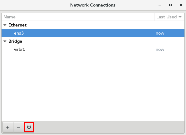 The
The
~]$ nm-connection-editor
The
Network Connections
window appears.
Select the ethernet connection you want to edit and click the gear wheel icon:
Figure 3.12. Edit a wired connection
Editing
dialog appears.
To connect to a network automatically and restrict connections, click the
General
tab, see
Section 3.4.3, “Common Configuration Options Using nm-connection-editor”
.
To configure the networking settings, click the
Ethernet
tab, see
the section called “Configuring 802.3 Link Settings with nm-connection-editor”
.
To configure 802.1X Security for a wired connection, click the
802.1X Security
tab, see
Section 5.2.4, “Configuring 802.1X Security for Wired with nm-connection-editor”
.
To configure the IPV4 settings, click the
IPV4 Settings
tab, see
the section called “Setting the Method for IPV4 Using nm-connection-editor”
.
To configure the IPV6 settings, click the
IPV6 Settings
tab, see
Section 5.5, “Configuring IPv6 Settings”
.
3.4.7. Configuring a Wi-Fi Connection with a GUI
This section explains how to use
NetworkManager
to configure a
Wi-Fi
(also known as wireless or 802.11
a/b/g/n
) connection to an Access Point. An Access Point is a device that allows wireless devices to connect to a network.
To configure a mobile broadband (such as 3G) connection, see
Section 3.4.9, “Configuring a Mobile Broadband Connection with a GUI”
.
Connecting Quickly to an Available Access Point
Procedure
Click on the network connection icon to activate the network connection icon's menu, see
Section 3.4.1, “Connecting to a Network Using the
control-center
GUI”
.
Locate the
Service Set Identifier
(
SSID
) of the access point in the list of
Wi-Fi
networks.
Click on the
SSID
of the network. A padlock symbol indicates the access point requires authentication. If the access point is secured, a dialog prompts you for an authentication key or password.
NetworkManager
tries to auto-detect the type of security used by the access point. If there are multiple possibilities,
NetworkManager
guesses the security type and presents it in the
Wi-Fi security
drop-down menu.
For WPA-PSK security (WPA with a passphrase) no choice is necessary.
For WPA Enterprise (802.1X) you have to specifically select the security, because that cannot be auto-detected.
Note that if you are unsure, try connecting to each type in turn.
Enter the key or passphrase in the
Password
field. Certain password types, such as a 40-bit WEP or 128-bit WPA key, are invalid unless they are of a requisite length. The
Connect
button will remain inactive until you enter a key of the length required for the selected security type. To learn more about wireless security, see
Section 5.2, “Configuring 802.1X Security”
.
If
NetworkManager
connects to the access point successfully, the network connection icon will change into a graphical indicator of the wireless connection's signal strength.
You can also edit the settings for one of these auto-created access point connections just as if you had added it yourself. The
Wi-Fi
page of the
Network
window has a
History
button. Clicking it reveals a list of all the connections you have ever tried to connect to. See
the section called “Editing an Existing Wi-Fi Connection”
Connecting to a Hidden Wi-Fi Network
All access points have a
Service Set Identifier
(
SSID
) to identify them. However, an access point may be configured not to broadcast its SSID, in which case it is
hidden
, and will not show up in
NetworkManager
's list of
Available
networks. You can still connect to a wireless access point that is hiding its SSID as long as you know its SSID, authentication method, and secrets. To connect to a hidden wireless network:
Procedure
Press the
Super
key to enter the Activities Overview, type
Settings
and then press
Enter
. Then, select the
Wi-Fi
menu entry on the left-hand side.
Select
Connect to Hidden Network
. There are two options:
If you have connected to the hidden network before:
Use the
Connection
drop-down to select the network.
Click
Connect
.
If not, proceed as follows:
Leave the
Connection
drop-down as
New
.
Enter the SSID of the hidden network.
Select its
Wi-Fi security
method.
Enter the correct authentication secrets.
Click
Connect
.
For more information on wireless security settings, see
Section 5.2, “Configuring 802.1X Security”
.
Configuring a New Wi-Fi Connection
Procedure
Select the
Wi-Fi
menu entry of
Settings
.
Click the Wi-Fi connection name that you want to connect to (by default, the same as the SSID).
If the
SSID
is not in range, see
the section called “Connecting to a Hidden Wi-Fi Network”
for more information.
If the SSID is in range, click the
Wi-Fi
connection profile on the right-hand side menu. A padlock symbol indicates a key or password is required. If requested, enter the authentication details.
Editing an Existing Wi-Fi Connection
You can edit an existing connection that you have tried or succeeded in connecting to in the past.
Procedure
Press the
Super
key to enter the Activities Overview, type
Settings
and press
Enter
.
Select
Wi-Fi
from the left-hand-side menu entry.
Select the gear wheel icon to the right of the Wi-Fi connection name that you want to edit, and the editing connection dialog appears. Note that if the network is not currently in range, click
History
to display past connections. The
Details
window shows the connection details.
Basic Configuration Options for a Wi-Fi Connection
To edit a Wi-Fi connection's settings, select
Identity
from the editing connection dialog. The following settings are available:

Figure 3.13. Basic Configuration Options for a Wi-Fi Connection
- SSID
-
The Service Set Identifier ( SSID ) of the access point (AP).
- BSSID
-
The Basic Service Set Identifier ( BSSID ) is the MAC address, also known as a hardware address , of the specific wireless access point you are connecting to when in Infrastructure mode. This field is blank by default, and you are able to connect to a wireless access point by SSID without having to specify its BSSID . If the BSSID is specified, it will force the system to associate to a specific access point only. For ad-hoc networks, the BSSID is generated randomly by the mac80211 subsystem when the ad-hoc network is created. It is not displayed by NetworkManager
- MAC address
-
Select the MAC address, also known as a hardware address , of the Wi-Fi interface to use. A single system could have one or more wireless network adapters connected to it. The MAC address field therefore allows you to associate a specific wireless adapter with a specific connection (or connections).
- Cloned Address
-
A cloned MAC address to use in place of the real hardware address. Leave blank unless required. The following settings are common to the most connection types: Connect automatically — Select this box if you want NetworkManager to auto-connect to this connection when it is available. See the section called “Editing an Existing Connection with control-center” for more information. Make available to other users — Select this box to create a connection available to all users on the system. Changing this setting may require root privileges. See Section 3.4.5, “Managing System-wide and Private Connection Profiles with a GUI” for details.
Making Further Wi-Fi Configurations
You can further configure an existing connection in the editing dialog.
To configure:
security authentication
for the wireless connection, click
Security
and proceed to
Section 5.2, “Configuring 802.1X Security”
.
IPv4
settings for the connection, click
IPv4
and proceed to
Section 5.4, “Configuring IPv4 Settings”
IPv6
settings for the connection, click
IPv6
and proceed to
Section 5.5, “Configuring IPv6 Settings”
.
Saving Your New (or Modified) Connection
Once you have finished editing the wireless connection, click the
Apply
button to save your configuration. Given a correct configuration, you can connect to your modified connection by selecting it from the network connection icon's menu. See
Section 3.4.1, “Connecting to a Network Using the
control-center
GUI”
for details on selecting and connecting to a network.
3.4.8. Configuring a VPN Connection with a GUI
IPsec
, provided by
Libreswan
, is the preferred method for creating a VPN.
Libreswan
is an open-source, user-space
IPsec
implementation for VPN. Configuring an
IPsec
VPN using the command line is documented in the
Red Hat Enterprise Linux 7 Security Guide
.
3.4.8.1. Establishing a VPN Connection with control-center
IPsec
, provided by
Libreswan
, is the preferred method for creating a VPN in Red Hat Enterprise Linux 7. For more information, see
Section 3.4.8, “Configuring a VPN Connection with a GUI”
.
The GNOME graphical user interface tool described below requires the
NetworkManager-libreswan-gnome
package. To install the package, run the following command as
root
:
~]# yum install NetworkManager-libreswan-gnome
See
Red Hat Enterprise Linux System Administrator's Guide
for more information on how to install new packages in Red Hat Enterprise Linux.
Establishing a Virtual Private Network (VPN) enables communication between your Local Area Network (LAN), and another, remote LAN. This is done by setting up a tunnel across an intermediate network such as the Internet. The VPN tunnel that is set up typically uses authentication and encryption. After successfully establishing a VPN connection using a secure tunnel, a VPN router or gateway performs the following actions upon the packets you transmit:
it adds an
Authentication Header
for routing and authentication purposes;
it encrypts the packet data; and,
it encloses the data in packets according to the Encapsulating Security Payload (ESP) protocol, which constitutes the decryption and handling instructions.
The receiving VPN router strips the header information, decrypts the data, and routes it to its intended destination (either a workstation or other node on a network). Using a network-to-network connection, the receiving node on the local network receives the packets already decrypted and ready for processing. The encryption and decryption process in a network-to-network VPN connection is therefore transparent to clients.
Because they employ several layers of authentication and encryption, VPNs are a secure and effective means of connecting multiple remote nodes to act as a unified intranet.
Adding a New IPsec VPN Connection
Procedure
Press the
Super
key to enter the Activities Overview, type
Settings
and press
Enter
. Then, select the
Network
menu entry and the
Network
settings tool appears, see
the section called “Configuring New Connections with control-center”
.
Click the plus button in the VPN entry.
The
Add VPN
window appears. For manually configuration, select
IPsec based VPN
.

Figure 3.14. Configuring VPN on IPsec mode
Identity
configuration form, you can specify the fields in the
General
and
Advanced
sections:

Figure 3.15. General and Advanced sections
General
section, you can specify:
- Gateway
-
The name or
IPaddress of the remote VPN gateway. - User name
-
If required, enter the user name associated with the VPN user's identity for authentication.
- User password
-
If required, enter the password associated with the VPN user's identity for authentication.
- Group name
-
The name of a VPN group configured on the remote gateway. In case it is blank, the IKEv1 Main mode is used instead of the default Aggressive mode.
- Secret
-
It is a pre-shared key which is used to initialize the encryption before the user's authentication. If required, enter the password associated with the group name.
- Phase1 Algorithms
-
If required, enter the algorithms to be used to authenticate and set up an encrypted channel.
- Phase2 Algorithms
-
If required, enter the algorithms to be used for the
IPsecnegotiations. - Domain
-
If required, enter the Domain Name. Configuring an
IPsecVPN without using NetworkManager , see Section 3.4.8, “Configuring a VPN Connection with a GUI” .
Editing an Existing VPN Connection
ProcedurePress the Super key to enter the Activities Overview, type Settings and press Enter . Then, select the Network menu entry and the Network settings tool appears, see the section called “Configuring New Connections with control-center” . Select the VPN connection you want to edit and click the gear wheel icon and edit theGeneralandAdvancedsections, see Section 3.4.8.1, “Establishing a VPN Connection with control-center” .
Saving Your New (or Modified) Connection and Making Further Configurations
Once you have finished editing your new VPN connection, click the
Save
button to save your customized configuration. If the profile was in use while being edited, power cycle the connection to make
NetworkManager
apply the changes. If the profile is OFF, set it to ON or select it in the network connection icon's menu. See
Section 3.4.1, “Connecting to a Network Using the
control-center
GUI”
for information on using your new or altered connection.
You can further configure an existing connection by selecting it in the
Network
window and clicking
Configure
to return to the
Editing
dialog.
Then, to configure:
IPv4
settings for the connection, click the
IPv4 Settings
tab and proceed to
Section 5.4, “Configuring IPv4 Settings”
.
3.4.8.2. Configuring a VPN Connection with nm-connection-editor
You can also use
nm-connection-editor
to add and configure a VPN connection. For doing that, proceed as follows:
Procedure
Enter
nm-connection-editor
in a terminal. The
Network Connections
window appears, see
Section 3.4.3, “Common Configuration Options Using nm-connection-editor”
.
Click the plus button. The
Choose a Connection Type
menu opens.
Select from the
VPN
menu entry, the
IPsec based VPN
option.
Click
Create
to open the
Editing
dialog and proceed to
the section called “Adding a New IPsec VPN Connection”
to edit the
General
and
Advanced
sections.
3.4.9. Configuring a Mobile Broadband Connection with a GUI
You can use
NetworkManager
's mobile broadband connection abilities to connect to the following
2G
and
3G
services:
2G —
GPRS
(
General Packet Radio Service
),
EDGE
(
Enhanced Data Rates for GSM Evolution
), or CDMA (Code Division Multiple Access).
3G —
UMTS
(
Universal Mobile Telecommunications System
),
HSPA
(
High Speed Packet Access
), or EVDO (EVolution Data-Only).
Your computer must have a mobile broadband device (modem), which the system has discovered and recognized, in order to create the connection. Such a device may be built into your computer (as is the case on many notebooks and netbooks), or may be provided separately as internal or external hardware. Examples include PC card, USB Modem or Dongle, mobile or cellular telephone capable of acting as a modem.
3.4.9.1. Configuring a Mobile Broadband Connection with nm-connection-editor
You can configure a mobile broadband connection using the GNOME
nm-connection-editor
.
Adding a New Mobile Broadband Connection
Procedure
Enter
nm-connection-editor
in a terminal. The
Network Connections
window appears, see
Section 3.4.3, “Common Configuration Options Using nm-connection-editor”
.
Click the plus button. The
Choose a Connection Type
menu opens.
Select the
Mobile Broadband
menu entry.
Click
Create
to open the
Set up a Mobile Broadband Connection
assistant.
Under
Create a connection for this mobile broadband device
, choose the 2G- or 3G-capable device you want to use with the connection. If the drop-down menu is inactive, this indicates that the system was unable to detect a device capable of mobile broadband. In this case, click
Cancel
, ensure that you do have a mobile broadband-capable device attached and recognized by the computer and then retry this procedure. Click the
Continue
button.
Select the country where your service provider is located from the list and click the
Continue
button.
Select your provider from the list or enter it manually. Click the
Continue
button.
Select your payment plan from the drop-down menu and confirm the
Access Point Name
(
APN
) is correct. Click the
Continue
button.
Review and confirm the settings and then click the
Apply
button.
Edit the mobile broadband-specific settings by referring to
the section called “Configuring the Mobile Broadband Tab”
Editing an Existing Mobile Broadband Connection
Procedure
Enter
nm-connection-editor
in a terminal. The
Network Connections
window appears.
Select the
Mobile Broadband
tab.
Select the connection you want to edit and click the gear wheel icon. See
Section 3.4.3, “Common Configuration Options Using nm-connection-editor”
for more information.
Edit the mobile broadband-specific settings by referring to
the section called “Configuring the Mobile Broadband Tab”
Configuring the Mobile Broadband Tab
If you have already added a new mobile broadband connection using the assistant (see
the section called “Adding a New Mobile Broadband Connection”
for instructions), you can edit the
Mobile Broadband
tab to disable roaming if home network is not available, assign a network ID, or instruct
NetworkManager
to prefer a certain technology (such as 3G or 2G) when using the connection.
- Number
-
The number that is dialed to establish a PPP connection with the GSM-based mobile broadband network. This field may be automatically populated during the initial installation of the broadband device. You can usually leave this field blank and enter the APN instead.
- Username
-
Enter the user name used to authenticate with the network. Some providers do not provide a user name, or accept any user name when connecting to the network.
- Password
-
Enter the password used to authenticate with the network. Some providers do not provide a password, or accept any password. Enter the Access Point Name ( APN ) used to establish a connection with the GSM-based network. Entering the correct APN for a connection is important because it often determines: how the user is billed for their network usage; whether the user has access to the Internet, an intranet, or a subnetwork.
Entering a
Network ID
causes
NetworkManager
to force the device to register only to a specific network. This can be used to ensure the connection does not roam when it is not possible to control roaming directly.
Any
— The default value of
Any
leaves the modem to select the fastest network.
3G (UMTS/HSPA)
— Force the connection to use only 3G network technologies.
2G (GPRS/EDGE)
— Force the connection to use only 2G network technologies.
Prefer 3G (UMTS/HSPA)
— First attempt to connect using a 3G technology such as HSPA or UMTS, and fall back to GPRS or EDGE only upon failure.
Prefer 2G (GPRS/EDGE)
— First attempt to connect using a 2G technology such as GPRS or EDGE, and fall back to HSPA or UMTS only upon failure.
Uncheck this box if you want
NetworkManager
to terminate the connection rather than transition from the home network to a roaming one, thereby avoiding possible roaming charges. If the box is checked,
NetworkManager
will attempt to maintain a good connection by transitioning from the home network to a roaming one, and vice versa.
If your device's
SIM
(
Subscriber Identity Module
) is locked with a
PIN
(
Personal Identification Number
), enter the PIN so that
NetworkManager
can unlock the device.
NetworkManager
must unlock the SIM if a PIN is required in order to use the device for any purpose.
CDMA and EVDO have fewer options. They do not have the
APN
,
Network ID
, or
Type
options.
Saving Your New (or Modified) Connection and Making Further Configurations
Once you have finished editing your mobile broadband connection, click the
Apply
button to save your customized configuration. If the profile was in use while being edited, power cycle the connection to make
NetworkManager
apply the changes. If the profile is OFF, set it to ON or select it in the network connection icon's menu. See
Section 3.4.1, “Connecting to a Network Using the
control-center
GUI”
for information on using your new or altered connection.
You can further configure an existing connection by selecting it in the
Network Connections
window and clicking
Edit
to return to the
Editing
dialog.
Then, to configure:
Point-to-point
settings for the connection, click the
PPP Settings
tab and proceed to
Section 5.6, “Configuring PPP (Point-to-Point) Settings”
;
IPv4
settings for the connection, click the
IPv4 Settings
tab and proceed to
Section 5.4, “Configuring IPv4 Settings”
; or,
IPv6
settings for the connection, click the
IPv6 Settings
tab and proceed to
Section 5.5, “Configuring IPv6 Settings”
.
3.4.10. Configuring a DSL Connection with a GUI
This section is intended for those installations which have a DSL card fitted within a host rather than the external combined DSL modem router combinations typical of private consumer or SOHO installations.
3.4.10.1. Configuring a DSL Connection with nm-connection-editor
You can configure a DSL connection using the GNOME
nm-connection-editor
.
Adding a New DSL Connection
Procedure
Enter
nm-connection-editor
in a terminal. The
Network Connections
window appears, see
Section 3.4.3, “Common Configuration Options Using nm-connection-editor”
.
Click the plus button.
The
Choose a Connection Type
list appears.
Select
DSL
and press the
Create
button.
The
Editing DSL Connection
1
window appears.
Editing an Existing DSL Connection
Procedure
Enter
nm-connection-editor
in a terminal. The
Network Connections
window appears.
Select the connection you want to edit and click the gear wheel icon. See
Section 3.4.3, “Common Configuration Options Using nm-connection-editor”
for more information.
Configuring the DSL Tab
- Username
-
Enter the user name used to authenticate with the service provider.
- Service
-
Leave blank unless otherwise directed by your service provider.
- Password
-
Enter the password supplied by the service provider.
Saving Your New (or Modified) Connection and Making Further Configurations
Once you have finished editing your DSL connection, click the
Apply
button to save your customized configuration. If the profile was in use while being edited, power cycle the connection to make
NetworkManager
apply the changes. If the profile is OFF, set it to ON or select it in the network connection icon's menu. See
Section 3.4.1, “Connecting to a Network Using the
control-center
GUI”
for information on using your new or altered connection.
You can further configure an existing connection by selecting it in the
Network Connections
window and clicking
Edit
to return to the
Editing
dialog.
To configure:
The MAC address and MTU
settings, click the
Wired
tab and proceed to
the section called “Basic Configuration Options ”
.
Point-to-point
settings for the connection, click the
PPP Settings
tab and proceed to
Section 5.6, “Configuring PPP (Point-to-Point) Settings”
.
IPv4
settings for the connection, click the
IPv4 Settings
tab and proceed to
Section 5.4, “Configuring IPv4 Settings”
.
3.5. Configuring IP Networking with ifcfg Files
As a system administrator, you can configure a network interface manually, editing the
ifcfg
files.
Interface configuration (ifcfg) files control the software interfaces for individual network devices. As the system boots, it uses these files to determine what interfaces to bring up and how to configure them. These files are usually named
ifcfg-
name
, where the suffix
name
refers to the name of the device that the configuration file controls. By convention, the
ifcfg
file's suffix is the same as the string given by the
DEVICE
directive in the configuration file itself.
Configuring an Interface with Static Network Settings Using ifcfg Files
For example, to configure an interface with static network settings using
ifcfg
files, for an interface with the name
enp1s0
, create a file with the name
ifcfg-enp1s0
in the
/etc/sysconfig/network-scripts/
directory, that contains:
For
IPv4
configuration
DEVICE=enp1s0 BOOTPROTO=none ONBOOT=yes PREFIX=24 IPADDR=10.0.1.27 ForIPv6configurationDEVICE=enp1s0 BOOTPROTO=none ONBOOT=yes IPV6INIT=yes IPV6ADDR=2001:db8::2/48 You do not need to specify the network or broadcast address as this is calculated automatically by ipcalc. For moreIPv6ifcfg configuration options, see nm-settings-ifcfg-rh(5) man page.Important
In Red Hat Enterprise Linux 7, the naming convention for network interfaces has been changed, as explained in Chapter 11, Consistent Network Device Naming. Specifying the hardware or MAC address usingHWADDRdirective can influence the device naming procedure.Configuring an Interface with Dynamic Network Settings Using ifcfg Files
To configure an interface named em1 with dynamic network settings usingifcfgfiles: Create a file with the nameifcfg-em1in the/etc/sysconfig/network-scripts/directory, that contains:DEVICE=em1 BOOTPROTO=dhcp ONBOOT=yes To configure an interface to send a different host name to thewhere ip-address is the address of aDHCPserver, add the following line to theifcfgfile:DHCP_HOSTNAME=hostnameTo configure an interface to send a different fully qualified domain name (FQDN) to theDHCPserver, add the following line to theifcfgfile:DHCP_FQDN=fully.qualified.domain.nameOnly one directive, eitherDHCP_HOSTNAMEorDHCP_FQDN, should be used in a givenifcfgfile. In case bothDHCP_HOSTNAMEandDHCP_FQDNare specified, only the latter is used. To configure an interface to use particularDNSservers, add the following lines to theifcfgfile: PEERDNS=no DNS1=ip-address DNS2=ip-addressDNSserver. This will cause the network service to update/etc/resolv.confwith the specifiedDNSservers specified. Only oneDNSserver address is necessary, the other is optional. To configure static routes in theifcfgfile, see Section 4.5, “Configuring Static Routes in ifcfg files”. By default, NetworkManager calls theDHCPclient, dhclient, when a profile has been set to obtain addresses automatically by settingBOOTPROTOtodhcpin an interface configuration file. IfDHCPis required, an instance of dhclient is started for every Internet protocol,IPv4andIPv6, on an interface. If NetworkManager is not running, or is not managing an interface, then the legacy network service will call instances of dhclient as required. For more details on dynamic IP addresses, see Section 1.2, “Comparing Static to Dynamic IP Addressing”. To apply the configuration: Reload the updated connection files:# nmcli connection reload3.5.1. Managing System-wide and Private Connection Profiles with ifcfg Files
The permissions correspond to theUSERSdirective in theifcfgfiles. If theUSERSdirective is not present, the network profile will be available to all users. As an example, the following command in anifcfgfile will make the connection available only to the users listed:USERS="joe bob alice"Also, you can set theUSERCTLdirective to manage the device: If you set yes, non-rootusers are allowed to control this device. If you set no, non-rootusers are not allowed to control this device.
3.6. Configuring IP Networking with ip Commands
As a system administrator, you can configure a network interface using the
ip
command, but but changes are not persistent across reboots; when you reboot, you will lose any changes.
The commands for the
ip
utility, sometimes referred to as
iproute2
after the upstream package name, are documented in the
man ip(8)
page. The package name in Red Hat Enterprise Linux 7 is
iproute
. If necessary, you can check that the
ip
utility is installed by checking its version number as follows:
~]$ ip -V
ip utility, iproute2-ss130716
The
ip
commands can be used to add and remove addresses and routes to interfaces in parallel with
NetworkManager
, which will preserve them and recognize them in
nmcli
,
nmtui
,
control-center
, and the D-Bus API.
To bring an interface down:
ip link set ifname down
ip link set
ifname
command sets a network interface in
IFF_UP
state and enables it from the kernel's scope. This is different from the
ifup
ifname
command for initscripts or
NetworkManager
's activation state of a device. In fact,
NetworkManager
always sets an interface up even if it is currently disconnected. Disconnecting the device through the
nmcli
tool, does not remove the
IFF_UP
flag. In this way,
NetworkManager
gets notifications about the carrier state.
Note that the
ip
utility replaces the
ifconfig
utility because the
net-tools
package (which provides
ifconfig
) does not support InfiniBand addresses.
For information about available OBJECTs, use the
ip help
command. For example:
ip link help
and
ip addr help
.
ip
commands given on the command line will not persist after a system restart. Where persistence is required, make use of configuration files (
ifcfg
files) or add the commands to a script.
Examples of using the command line and configuration files for each task are included after
nmtui
and
nmcli
examples but before explaining the use of one of the graphical user interfaces to
NetworkManager
, namely,
control-center
and
nm-connection-editor
.
The
ip
utility can be used to assign
IP
addresses to an interface with the following form:
ip addr [ add | del ] address dev ifname
Assigning a Static Address Using ip Commands
To assign an
IP
address to an interface:
~]#Further examples and command options can be found in theip address add 10.0.0.3/24 dev enp1s0You can view the address assignment of a specific device: ~]#ip addr show dev enp1s02: enp1s0: <BROADCAST,MULTICAST,UP,LOWER_UP> mtu 1500 qdisc pfifo_fast state UP qlen 1000 link/ether f0:de:f1:7b:6e:5f brd ff:ff:ff:ff:ff:ff inet 10.0.0.3/24 brd 10.0.0.255 scope global global enp1s0 valid_lft 58682sec preferred_lft 58682sec inet6 fe80::f2de:f1ff:fe7b:6e5f/64 scope link valid_lft forever preferred_lft forever
ip-address(8)
manual page.
Configuring Multiple Addresses Using ip Commands
As the
ip
utility supports assigning multiple addresses to the same interface it is no longer necessary to use the alias interface method of binding multiple addresses to the same interface. The
ip
command to assign an address can be repeated multiple times in order to assign multiple address. For example:
~]#For more details on the commands for the ip utility, see theip address add 192.168.2.223/24 dev enp1s0~]#ip address add 192.168.4.223/24 dev enp1s0~]#ip addr3: enp1s0: <BROADCAST,MULTICAST,UP,LOWER_UP> mtu 1500 qdisc pfifo_fast state UP qlen 1000 link/ether 52:54:00:fb:77:9e brd ff:ff:ff:ff:ff:ff inet 192.168.2.223/24 scope global enp1s0 inet 192.168.4.223/24 scope global enp1s0
ip(8)
manual page.
ip
commands given on the command line will
not
persist after a system restart.
3.7. Configuring IP Networking from the Kernel Command line
When connecting to the root file system on an iSCSI target from an interface, the network settings are not configured on the installed system. For solution of this problem:
Install the
dracut
utility. For information on using
dracut
, see
Red Hat Enterprise Linux System Administrator's Guide
Set the configuration using the
ip
option on the kernel command line:
ip<client-IP-number>:[<server-id>]:<gateway-IP-number>:<netmask>:<client-hostname>:<interface>:{dhcp|dhcp6|auto6|on|any|none|off}
dhcp
- DHCP configuration
dhpc6
- DHCP IPv6 configuration
auto6
- automatic IPv6 configuration
on
,
any
- any protocol available in the kernel (default)
none
,
off
- no autoconfiguration, static network configuration
For example:
ip=192.168.180.120:192.168.180.100:192.168.180.1:255.255.255.0::enp1s0:offSet the name server configuration:
nameserver=srv1 [nameserver=srv2 [nameserver=srv3 […]]]The dracut utility sets up a network connection and generates new
ifcfg
files that can be copied to the
/etc/sysconfig/network-scripts/
file.
3.8. Enabling IP Multicast with IGMP
The Internet Group Management Protocol (IGMP) enables the administrator to manage routing and subscription to multicast traffic between networks, hosts, and routers. The kernel in Red Hat Enterprise Linux supports IGMPv3.
To display multicast information, use the
ip maddr show
subcommand, for example:
~]$ ip maddr show dev br0
8: br0
inet 224.0.0.1
inet6 ff02::1
inet6 ff01::1
[output truncated]
Alternatively, look for the
MULTICAST
string in the
ip link show
command output, for example:
~]$ ip link show br0
8: br0: <BROADCAST,MULTICAST,UP,LOWER_UP> mtu 1500 qdisc noqueue state UP mode DEFAULT qlen 1000
link/ether 6c:0b:84:67:fe:63 brd ff:ff:ff:ff:ff:ff
To disable multicast on a device and to check that multicast is disabled on the
br0
device:
~]#ip link set multicast off dev br0~]$ip link show br08: br0: <BROADCAST,UP,LOWER_UP> mtu 1500 qdisc noqueue state UP mode DEFAULT qlen 1000 link/ether 6c:0b:84:67:fe:63 brd ff:ff:ff:ff:ff:ff
The missing
MULTICAST
string indicates that multicast is disabled.
To enable multicast on the
br0
device and to check it is enabled:
~]#ip link set multicast on dev br0~]$ip link show br08: br0: <BROADCAST,MULTICAST,UP,LOWER_UP> mtu 1500 qdisc noqueue state UP mode DEFAULT qlen 1000 link/ether 6c:0b:84:67:fe:63 brd ff:ff:ff:ff:ff:ff
See the
ip Command Cheat Sheet for Red Hat Enterprise Linux
article and the
ip(8)
man page for more information.
To check current version of IGMP and IP addresses subscribed for multicasting, see the
/proc/net/igmp
file:
~]$ cat /proc/net/igmp
Note
IGMP is not enabled in
firewalld
by default. To enable IGMP for a zone:
~]# firewall-cmd --zone=zone-name --add-protocol=igmp
See the
Using Firewalls
chapter in the
Red Hat Enterprise Linux Security Guide
for more information.
3.9. Additional Resources
Installed Documentation
ip
(8)
man page — Describes the
ip
utility's command syntax.
nmcli
(1)
man page — Describes
NetworkManager
's command‐line tool.
nmcli-examples
(5)
man page — Gives examples of
nmcli
commands.
nm-settings
(5)
man page — Describes
NetworkManager
properties and their settings.
nm-settings-ifcfg-rh
(5)
man page — Describes
ifcfg-rh
settings plug-in.
Online Documentation
Describes
IPsec
based VPN and its configuration. Describes the use of authenticated
DNS
queries using DNSSEC.
Describes the CIDR Address Assignment and Aggregation Strategy, including variable-length subnetting.
Describes the range of
IPv4
addresses reserved for private use.
Describes the global and other specialized
IPv4
address blocks that have been assigned by the Internet Assigned Numbers Authority (IANA).
Chapter 4. Configuring Static Routes and the Default Gateway
This chapter covers the configuration of static routes and the default gateway.
4.1. Introduction to Understanding Routing and Gateway
Routing is a mechanism that allows a system to find the network path to another system. Routing is often handled by devices on the network dedicated to routing (although any device can be configured to perform routing). Therefore, it is often not necessary to configure static routes on Red Hat Enterprise Linux servers or clients. Exceptions include traffic that must pass through an encrypted VPN tunnel or traffic that should take a specific route for reasons of cost or security. A host's routing table will be automatically populated with routes to directly connected networks. The routes examine when the network interfaces are
“
up
”
. In order to reach a remote network or host, the system is given the address of a gateway to which traffic should be sent.
When a host's interface is configured by
DHCP
, an address of a gateway that leads to an upstream network or the Internet is usually assigned. This gateway is usually referred to as the default gateway as it is the gateway to use if no better route is known to the system (and present in the routing table). Network administrators often use the first or last host
IP
address in the network as the gateway address; for example,
192.168.10.1
or
192.168.10.254
. Not to be confused by the address which represents the network itself; in this example,
192.168.10.0
, or the subnet's broadcast address; in this example
192.168.10.255
. The default gateway is traditionally a network router. The default gateway is for any and all traffic which is not destined for the local network and for which no preferred route is specified in the routing table.
To expand your expertise, you might also be interested in the
Red Hat System Administration I (RH124)
training course.
4.2. Configuring Static Routes Using nmcli
To configure static routes using the
nmcli
tool, use one of the following:
the nmcli command line
the nmcli interactive editor
Example 4.1. Configuring Static Routes Using nmcli
To configure a static route for an existing Ethernet connection using the command line:
~]# nmcli connection modify enp1s0 +ipv4.routes "192.168.122.0/24 10.10.10.1"
This will direct traffic for the
192.168.122.0/24
subnet to the gateway at
10.10.10.1
Example 4.2. Configuring Static Routes with nmcli Editor
To configure a static route for an Ethernet connection using the interactive editor:
~]$ nmcli con edit ens3
===| nmcli interactive connection editor |===
Editing existing '802-3-ethernet' connection: 'ens3'
Type 'help' or '?' for available commands.
Type 'describe [<setting>.<prop>]' for detailed property description.
You may edit the following settings: connection, 802-3-ethernet (ethernet), 802-1x, dcb, ipv4, ipv6, tc, proxy
nmcli> set ipv4.routes 192.168.122.0/24 10.10.10.1
nmcli> save persistent
Connection 'ens3' (23f8b65a-8f3d-41a0-a525-e3bc93be83b8) successfully updated.
nmcli> quit
4.3. Configuring Static Routes with GUI
To set a static route, open the
IPv4
or
IPv6
settings window for the connection you want to configure. See
Section 3.4.1, “Connecting to a Network Using the
control-center
GUI”
for instructions on how to do that.
- Routes
-
Address — Enter the
IPaddress of a remote network, sub-net, or host. Netmask — The netmask or prefix length of theIPaddress entered above. Gateway — TheIPaddress of the gateway leading to the remote network, sub-net, or host entered above. Metric — A network cost, a preference value to give to this route. Lower values will be preferred over higher values. - Automatic
-
When Automatic is ON , routes from
RAorDHCPare used, but you can also add additional static routes. When OFF , only static routes you define are used. - Use this connection only for resources on its network
-
Select this check box to prevent the connection from becoming the default route. Typical examples are where a connection is a VPN tunnel or a leased line to a head office and you do not want any Internet-bound traffic to pass over the connection. Selecting this option means that only traffic specifically destined for routes learned automatically over the connection or entered here manually will be routed over the connection.
4.4. Configuring Static Routes with ip commands
As a system administrator, you can configure static routes using the
ip route
command.
To display the
IP
routing table, use the
ip route
command. For example:
~]$ ip route default via 192.168.122.1 dev ens9 proto static metric 1024 192.168.122.0/24 dev ens9 proto kernel scope link src 192.168.122.107 192.168.122.0/24 dev enp1s0 proto kernel scope link src 192.168.122.126The
ip route
commands take the following form:
ip route [ add | del | change | append | replace ] destination-address
See the
ip-route(8)
man page for more details on the options and formats.
To add a static route to a host address, in other words to a single IP address:
~]#where 192.0.2.1 is theip route add192.0.2.1 via 10.0.0.1 [devinterface]
IP
address of the host in dotted decimal notation,
10.0.0.1
is the next hop address and
interface
is the exit interface leading to the next hop.
To add a static route to a network, in other words to an
IP
address representing a range of
IP
addresses:
~]#where 192.0.2.0 is theip route add192.0.2.0/24 via 10.0.0.1 [devinterface]
IP
address of the destination network in dotted decimal notation and
/24
is the network prefix. The network prefix is the number of enabled bits in the subnet mask. This format of network address slash network prefix length is sometimes referred to as
classless inter-domain routing
(
CIDR
) notation.
To remove the assigned static route:
~]# ip route del 192.0.2.1
Any changes that you make to the routing table using
ip route
do not persist across system reboots. To permanently configure static routes, you can configure them by creating a
route-
interface
file in the
/etc/sysconfig/network-scripts/
directory for the interface. For example, static routes for the
enp1s0
interface would be stored in the
/etc/sysconfig/network-scripts/route-
enp1s0
file. Any changes that you make to a
route-
interface
file do not take effect until you restart either the network service or the interface. The
route-
interface
file has two formats:
ip
command arguments, see
the section called “Static Routes Using the IP Command Arguments Format”
.
network/netmask directives, see
the section called “Static Routes Using the Network/Netmask Directives Format”
.
See the
ip-route(8)
man page for more information on the
ip route
command.
4.5. Configuring Static Routes in ifcfg files
Static routes set using
ip
commands at the command prompt will be lost if the system is shutdown or restarted. To configure static routes to be persistent after a system restart, they must be placed in per-interface configuration files in the
/etc/sysconfig/network-scripts/
directory. The file name should be of the format
route-
interface
. There are two types of commands to use in the configuration files:
Static Routes Using the IP Command Arguments Format
If required in a per-interface configuration file, for example
/etc/sysconfig/network-scripts/route-enp1s0
, define a route to a default gateway on the first line. This is only required if the gateway is not set through
DHCP
and is not set globally in the
/etc/sysconfig/network
file:
default via 192.168.1.1 dev interface
where
192.168.1.1
is the
IP
address of the default gateway. The
interface
is the interface that is connected to, or can reach, the default gateway. The
dev
option can be omitted, it is optional. Note that this setting takes precedence over a setting in the
/etc/sysconfig/network
file.
If a route to a remote network is required, a static route can be specified as follows. Each line is parsed as an individual route:
10.10.10.0/24 via 192.168.1.1 [dev interface]
where
10.10.10.0/24
is the network address and prefix length of the remote or destination network. The address
192.168.1.1
is the
IP
address leading to the remote network. It is preferably the
next hop address
but the address of the exit interface will work. The
“
next hop
”
means the remote end of a link, for example a gateway or router. The
dev
option can be used to specify the exit interface
interface
but it is not required. Add as many static routes as required.
The following is an example of a
route-
interface
file using the
ip
command arguments format. The default gateway is
192.168.0.1
, interface
enp1s0
and a leased line or WAN connection is available at
192.168.0.10
. The two static routes are for reaching the
10.10.10.0/24
network and the
172.16.1.10/32
host:
default via 192.168.0.1 dev enp1s0 10.10.10.0/24 via 192.168.0.10 dev enp1s0 172.16.1.10/32 via 192.168.0.10 dev enp1s0
In the above example, packets going to the local
192.168.0.0/24
network will be directed out the interface attached to that network. Packets going to the
10.10.10.0/24
network and
172.16.1.10/32
host will be directed to
192.168.0.10
. Packets to unknown, remote, networks will use the default gateway therefore static routes should only be configured for remote networks or hosts if the default route is not suitable. Remote in this context means any networks or hosts that are not directly attached to the system.
For
IPv6
configuration, an example of a
route6-
interface
file in
ip route
format:
2001:db8:1::/48 via 2001:db8::1 metric 2048 2001:db8:2::/48Specifying an exit interface is optional. It can be useful if you want to force traffic out of a specific interface. For example, in the case of a VPN, you can force traffic to a remote network to pass through a tun0 interface even when the interface is in a different subnet to the destination network. The
ip route
format can be used to specify a source address. For example:
10.10.10.0/24 via 192.168.0.10 src 192.168.0.2To define an existing policy-based routing configuration, which specifies multiple routing tables, see Section 4.5.1, “Understanding Policy-routing” .
Important
If the default gateway is already assigned by
DHCP
and if the same gateway with the same metric is specified in a configuration file, an error during start-up, or when bringing up an interface, will occur. The follow error message may be shown: "RTNETLINK answers: File exists". This error may be ignored.
Static Routes Using the Network/Netmask Directives Format
You can also use the network/netmask directives format for
route-
interface
files. The following is a template for the network/netmask format, with instructions following afterwards:
ADDRESS0=10.10.10.0
NETMASK0=255.255.255.0
GATEWAY0=192.168.1.1
-
ADDRESS0= 10.10.10.0is the network address of the remote network or host to be reached.NETMASK0= 255.255.255.0is the netmask for the network address defined withADDRESS0= 10.10.10.0.GATEWAY0= 192.168.1.1is the default gateway, or anIPaddress that can be used to reachADDRESS0= 10.10.10.0The following is an example of aroute- interfacefile using the network/netmask directives format. The default gateway is192.168.0.1but a leased line or WAN connection is available at192.168.0.10. The two static routes are for reaching the10.10.10.0/24and172.16.1.0/24networks:ADDRESS0=10.10.10.0 NETMASK0=255.255.255.0 GATEWAY0=192.168.0.10 ADDRESS1=172.16.1.10 NETMASK1=255.255.255.0 GATEWAY1=192.168.0.10
Subsequent static routes must be numbered sequentially, and must not skip any values. For example,ADDRESS0,ADDRESS1,ADDRESS2, and so on. By default, forwarding packets from one interface to another, or out of the same interface, is disabled for security reasons. This prevents the system acting as a router for external traffic. If you need the system to route external traffic, such as when sharing a connection or configuring a VPN server, you will need to enable IP forwarding. See the Red Hat Enterprise Linux 7 Security Guide for more details.4.5.1. Understanding Policy-routing
Policy-routingalso known as source-routing, is a mechanism for more flexible routing configurations. Routing decisions are commonly made based on the destination IP address of a package.Policy-routingallows more flexibility to select routes based on other routing properties, such as source IP address, source port, protocol type. Routing tables stores route information about networks. They are identified by either numeric values or names, which can be configured in the/etc/iproute2/rt_tablesfile. The default table is identified with254. Usingpolicy-routing, you also need rules. Rules are used to select a routing table, based on certain properties of packets. For initscripts, the routing table is a property of the route that can be configured through the table argument. Theip routeformat can be used to define an existing policy-based routing configuration, which specifies multiple routing tables: 10.10.10.0/24 via 192.168.0.10 table 1 10.10.10.0/24 via 192.168.0.10 table 2 To specify routing rules in initscripts, edit them to the/etc/sysconfig/network-scripts/rule- enp1s0file forIPv4or to the/etc/sysconfig/network-scripts/rule6- enp1s0file forIPv6. NetworkManager supports policy-routing, but rules are not supported yet. The rules must be configured by the user running a custom script. For each manual static route, a routing table can be selected:ipv4.route-tableforIPv4ipv6.route-tableforIPv6. By setting routes to a particular table, all routes fromDHCP,autoconf6,DHCP6are placed in that specific table. In addition, all routes for subnets that have already configured addresses, are placed in the corresponding routing table. For example, if you configure the 192.168.1.10/24 address, the 192.168.1.0/24 subnet is contained in ipv4.route-table. For more details aboutpolicy-routingrules, see theip-rule(8)man page. For routing tables, see theip-route(8)man page.
4.6. Configuring the Default Gateway
The default gateway is determined by the network scripts which parse the
/etc/sysconfig/network
file first and then the network interface
ifcfg
files for interfaces that are
“
up
”
. The
ifcfg
files are parsed in numerically ascending order, and the last GATEWAY directive to be read is used to compose a default route in the routing table.
You can specify the default route using the GATEWAY directive, either globally or in interface-specific configuration files. However, in Red Hat Enterprise Linux the use of the global
/etc/sysconfig/network
file is deprecated, and specifying the gateway should now only be done in per-interface configuration files.
In dynamic network environments, where mobile hosts are managed by
NetworkManager
, gateway information is likely to be interface specific and is best left to be assigned by
DHCP
. In special cases where it is necessary to influence
NetworkManager
's selection of the exit interface to be used to reach a gateway, make use of the
DEFROUTE=no
command in the
ifcfg
files for those interfaces which do not lead to the default gateway.
Chapter 5. Configuring Network Connection Settings
This chapter describes various configurations of the network connection settings and shows how to configure them by using
NetworkManager
.
5.1. Configuring 802.3 Link Settings
You can configure the 802.3 link settings of an Ethernet connection by modifying the following configuration parameters:
802-3-ethernet.auto-negotiate
802-3-ethernet.speed
802-3-ethernet.duplex
You can configure the 802.3 link settings to three main modes:
Ignore link negotiation
Enforce auto-negotiation activation
Manually set the
speed
and
duplex
link settings
Ignoring link negotiation
In this case,
NetworkManager
ignores link configuration for an ethernet connection, keeping the already configuration on the device.
To ignore link negotiation, set the following parameters:
802-3-ethernet.auto-negotiate = no
802-3-ethernet.speed = 0
802-3-ethernet.duplex = NULL
Important
If the
auto-negotiate
parameter is set to
no
, but the
speed
and
duplex
values are not set, that does not mean that auto-negotiation is disabled.
Enforcing auto-negotiation activation
In this case,
NetworkManager
enforces auto-negotiation on a device.
To enforce auto-negotiation activation, set the following options:
802-3-ethernet.auto-negotiate = yes
802-3-ethernet.speed = 0
802-3-ethernet.duplex = NULL
Manually setting the link speed and duplex
In this case, you can manually configure the
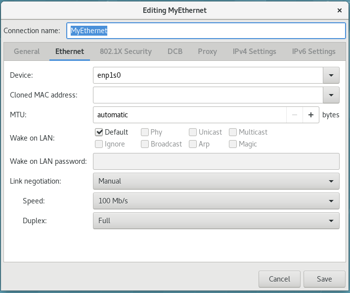
5.3. Using
speed
and
duplex
settings on the link.
To manually set the
speed
and
duplex
link settings, set the aforementioned parameters as follows:
802-3-ethernet.auto-negotiate = no
802-3-ethernet.speed = [speed in Mbit/s]
802-3-ethernet.duplex = [half |full]
Important
Make sure to set both the
speed
and the
duplex
values, otherwise
NetworkManager
does not update the link configuration.
As a system administrator, you can configure 802.3 link settings using one of the following options:
the
nmcli
tool
the
nm-connection-editor
utility
Configuring 802.3 Link Settings with the nmcli Tool
Procedure
Create a new ethernet connection for the
enp1s0
device.
Set the 802.3 link setting to a configuration of your choice. For details, see
Section 5.1, “Configuring 802.3 Link Settings”
For example, to manually set the
speed
option
100 Mbit/s
and
duplex
to
full
:
nmcli connection add con-name MyEthernet type ethernet ifname enp1s0 \
802-3-ethernet.auto-negotiate no \
802-3-ethernet.speed 100 \
802-3-ethernet.duplex full
Configuring 802.3 Link Settings with nm-connection-editor
Procedure
Enter
nm-connection-editor
in a terminal.
Select the ethernet connection you want to edit and click the gear wheel icon to move to the editing dialog. See
Section 3.4.3, “Common Configuration Options Using nm-connection-editor”
for more information.
Select the link negotiation of your choice.
Ignore
: link configuration is skipped (default).
Automatic
: link auto-negotiation is enforced on the device.
Manual
: the
Speed
and
Duplex
options can be specified to enforce the link negotiation.
Figure 5.1. Configure 802.3 link settings using nm-connection-editor
5.2. Configuring 802.1X Security
802.1X security is the name of the IEEE standard for
port-based Network Access Control
(
PNAC
). It is also called
WPA Enterprise
. 802.1X security is a way of controlling access to a
logical network
from a physical one. All clients who want to join the logical network must authenticate with the server (a router, for example) using the correct 802.1X authentication method.
802.1X security is most often associated with securing wireless networks (WLANs), but can also be used to prevent intruders with physical access to the network (LAN) from gaining entry.
In the past,
DHCP
servers were configured not to lease
IP
addresses to unauthorized users, but for various reasons this practice is both impractical and insecure, and thus is no longer recommended. Instead, 802.1X security is used to ensure a logically-secure network through port-based authentication.
802.1X provides a framework for WLAN and LAN access control and serves as an envelope for carrying one of the Extensible Authentication Protocol (EAP) types. An EAP type is a protocol that defines how security is achieved on the network.
5.2.1. Configuring 802.1X Security for Wi-Fi with nmcli
Procedure
Set the authenticated
key-mgmt
(key management) protocol. It configures the keying mechanism for a secure
wifi
connection. See the
nm-settings
(5)
man page for more details on properties.
Configure the 802-1x authentication settings. For the Transport Layer Security (TLS) authentication, see
the section called “Configuring TLS Settings”
.
Table 5.1. The 802-1x authentication settings
| 802-1x authentication setting | Name | |
|---|---|---|
| 802-1x.identity | Identity | |
| 802-1x.ca-cert | CA certificate | |
| 802-1x.client-cert | User certificate | |
| 802-1x.private-key | Private key | |
| 802-1x.private-key-password | Private key password |
For example, to configure WPA2 Enterprise using the EAP-TLS authentication method, apply the following settings:
nmcli c add type wifi ifname wlo61s0 con-name 'My Wifi Network' \
802-11-wireless.ssid 'My Wifi' \
802-11-wireless-security.key-mgmt wpa-eap \
802-1x.eap tls \
802-1x.identity [email protected] \
802-1x.ca-cert /etc/pki/my-wifi/ca.crt \
802-1x.client-cert /etc/pki/my-wifi/client.crt \
802-1x.private-key /etc/pki/my-wifi/client.key \
802-1x.private-key-password s3cr3t
5.2.2. Configuring 802.1X Security for Wired with nmcli
To configure a
wired
connection using the
nmcli
tool, follow the same procedure as for a
wireless
connection, except the
802-11-wireless.ssid
and
802-11-wireless-security.key-mgmt
settings.
5.2.3. Configuring 802.1X Security for Wi-Fi with a GUI
Procedure
Open the
Network
window (see
Section 3.4.1, “Connecting to a Network Using the
control-center
GUI”
).
Select a
Wireless
network interface from the right-hand-side menu. If necessary, set the symbolic power button to
ON
and check that your hardware switch is on.
Either select the connection name of a new connection, or click the gear wheel icon of an existing connection profile, for which you want to configure 802.1X security. In the case of a new connection, complete any authentication steps to complete the connection and then click the gear wheel icon.
Select
Security
.
The following configuration options are available:
- Security
-
None — Do not encrypt the Wi-Fi connection. WEP 40/128-bit Key — Wired Equivalent Privacy (WEP), from the IEEE 802.11 standard. Uses a single pre-shared key (PSK). WEP 128-bit Passphrase — An MD5 hash of the passphrase will be used to derive a WEP key. LEAP — Lightweight Extensible Authentication Protocol, from Cisco Systems. Dynamic WEP (802.1X) — WEP keys are changed dynamically. Use with the section called “Configuring TLS Settings” WPA & WPA2 Personal — Wi-Fi Protected Access (WPA), from the draft IEEE 802.11i standard. A replacement for WEP. Wi-Fi Protected Access II (WPA2), from the 802.11i-2004 standard. Personal mode uses a pre-shared key (WPA-PSK). WPA & WPA2 Enterprise — WPA for use with a RADIUS authentication server to provide IEEE 802.1X network access control. Use with the section called “Configuring TLS Settings”
- Password
-
Enter the password to be used in the authentication process. From the drop-down menu select one of the following security methods: LEAP , Dynamic WEP (802.1X) , or WPA & WPA2 Enterprise . See the section called “Configuring TLS Settings” for descriptions of which extensible authentication protocol ( EAP ) types correspond to your selection in the Security drop-down menu.
5.2.4. Configuring 802.1X Security for Wired with nm-connection-editor
Procedure
Enter the
nm-connection-editor
in a terminal.
~]$ nm-connection-editor
The
Network Connections
window appears.
Select the ethernet connection you want to edit and click the gear wheel icon, see
Section 3.4.6.2, “Configuring a Wired Connection with nm-connection-editor”
.
Select
Security
and set the symbolic power button to
ON
to enable settings configuration.
Select from one of following authentication methods:
Select
TLS
for
Transport Layer Security
and proceed to
the section called “Configuring TLS Settings”
;
Select
FAST
for
Flexible Authentication through Secure Tunneling
and proceed to
the section called “Configuring Tunneled TLS Settings”
;
Select
Tunneled TLS
for
Tunneled Transport Layer Security
, otherwise known as TTLS, or EAP-TTLS and proceed to
the section called “Configuring Tunneled TLS Settings”
;
Select
Protected EAP (PEAP)
for
Protected Extensible Authentication Protocol
and proceed to
the section called “Configuring Protected EAP (PEAP) Settings”
.
Configuring TLS Settings
With Transport Layer Security (TLS), the client and server mutually authenticate using the TLS protocol. The server demonstrates that it holds a digital certificate, the client proves its own identity using its client-side certificate, and key information is exchanged. Once authentication is complete, the TLS tunnel is no longer used. Instead, the client and server use the exchanged keys to encrypt data using AES, TKIP or WEP.
The fact that certificates must be distributed to all clients who want to authenticate means that the EAP-TLS authentication method is very strong, but also more complicated to set up. Using TLS security requires the overhead of a public key infrastructure (PKI) to manage certificates. The benefit of using TLS security is that a compromised password does not allow access to the (W)LAN: an intruder must also have access to the authenticating client's private key.
NetworkManager
does not determine the version of TLS supported.
NetworkManager
gathers the parameters entered by the user and passes them to the daemon,
wpa_supplicant
, that handles the procedure. It in turn uses OpenSSL to establish the TLS tunnel. OpenSSL itself negotiates the SSL/TLS protocol version. It uses the highest version both ends support.
To configure TLS settings, follow the procedure described in
Section 5.2.4, “Configuring 802.1X Security for Wired with nm-connection-editor”
. The following configuration settings are available:
- Identity
-
Provide the identity of this server.
- User certificate
-
Click to browse for, and select, a personal X.509 certificate file encoded with Distinguished Encoding Rules ( DER ) or Privacy Enhanced Mail ( PEM ).
- CA certificate
-
Click to browse for, and select, an X.509 certificate authority certificate file encoded with Distinguished Encoding Rules ( DER ) or Privacy Enhanced Mail ( PEM ).
- Private key
-
Click to browse for, and select, a private key file encoded with Distinguished Encoding Rules ( DER ), Privacy Enhanced Mail ( PEM ), or the Personal Information Exchange Syntax Standard ( PKCS #12 ).
- Private key password
-
Enter the password for the private key in the Private key field. Select Show password to make the password visible as you type it.
Configuring FAST Settings
To configure FAST settings, follow the procedure described in
Section 5.2.4, “Configuring 802.1X Security for Wired with nm-connection-editor”
. The following configuration settings are available:
- Anonymous Identity
-
Provide the identity of this server.
- PAC provisioning
-
Select the check box to enable and then select from Anonymous , Authenticated , and Both .
- PAC file
-
Click to browse for, and select, a protected access credential ( PAC ) file.
- Inner authentication
-
GTC — Generic Token Card. MSCHAPv2 — Microsoft Challenge Handshake Authentication Protocol version 2.
- Username
-
Enter the user name to be used in the authentication process.
- Password
-
Enter the password to be used in the authentication process.
Configuring Tunneled TLS Settings
To configure Tunneled TLS settings, follow the procedure described in
Section 5.2.4, “Configuring 802.1X Security for Wired with nm-connection-editor”
. The following configuration settings are available:
- Anonymous identity
-
This value is used as the unencrypted identity.
- CA certificate
-
Click to browse for, and select, a Certificate Authority's certificate.
- Inner authentication
-
PAP — Password Authentication Protocol. MSCHAP — Challenge Handshake Authentication Protocol. MSCHAPv2 — Microsoft Challenge Handshake Authentication Protocol version 2. CHAP — Challenge Handshake Authentication Protocol.
- Username
-
Enter the user name to be used in the authentication process.
- Password
-
Enter the password to be used in the authentication process.
Configuring Protected EAP (PEAP) Settings
To configure Protected EAP (PEAP) settings, follow the procedure described in
Section 5.2.4, “Configuring 802.1X Security for Wired with nm-connection-editor”
. The following configuration settings are available:
- Anonymous Identity
-
This value is used as the unencrypted identity.
- CA certificate
-
Click to browse for, and select, a Certificate Authority's certificate.
- PEAP version
-
The version of Protected EAP to use. Automatic, 0 or 1.
- Inner authentication
-
MSCHAPv2 — Microsoft Challenge Handshake Authentication Protocol version 2. MD5 — Message Digest 5, a cryptographic hash function. GTC — Generic Token Card.
- Username
-
Enter the user name to be used in the authentication process.
- Password
-
Enter the password to be used in the authentication process.
5.3. Using
MACsec
with
wpa_supplicant
and
NetworkManager
Media Access Control Security
(
MACsec
, IEEE 802.1AE) encrypts and authenticates all traffic in LANs with the GCM-AES-128 algorithm.
MACsec
can protect not only
IP
but also Address Resolution Protocol (ARP), Neighbor Discovery (ND), or
DHCP
. While
IPsec
operates on the network layer (layer 3) and
SSL
or
TLS
on the application layer (layer 7),
MACsec
operates in the data link layer (layer 2). Combine
MACsec
with security protocols for other networking layers to take advantage of different security features that these standards provide.
To enable
MACsec
with a switch that performs authentication using a pre-shared Connectivity Association Key/CAK Name (CAK/CKN) pair:
Procedure
Create a CAK/CKN pair. For example, the following command generates a 16-byte key in hexadecimal notation:
~]$ dd if=/dev/urandom count=16 bs=1 2> /dev/null | hexdump -e '1/2 "%02x"'
Create the
wpa_supplicant.conf
configuration file and add the following lines to it:
ctrl_interface=/var/run/wpa_supplicant
eapol_version=3
ap_scan=0
fast_reauth=1
network={
key_mgmt=NONE
eapol_flags=0
macsec_policy=1
mka_cak=0011... # 16 bytes hexadecimal
mka_ckn=2233... # 32 bytes hexadecimal
Use the values from the previous step to complete the mka_cak and mka_ckn lines in the wpa_supplicant.conf configuration file.
See the wpa_supplicant.conf(5) man page for more information.
Assuming you are using wlp61s0 to connect to your network, start wpa_supplicant using the following command:
~]# wpa_supplicant -i wlp61s0 -Dmacsec_linux -c wpa_supplicant.conf
Instead of creating and editing the
wpa_supplicant.conf
file, Red Hat recommends using the
nmcli
command to configure
wpa_supplicant
equivalently as in the previous steps. The following example assumes that you already have a 16-byte hexadecimal CAK (
$MKA_CAK
) and a 32-byte hexadecimal CKN (
$MKA_CKN
):
~]# nmcli connection add type macsec \ con-name test-macsec+ ifname macsec0 \ connection.autoconnect no \ macsec.parent wlp61s0 macsec.mode psk \ macsec.mka-cak $MKA_CAK \ macsec.mka-cak-flags 0 \ macsec.mka-ckn $MKA_CKN ~]# nmcli connection up test-macsec+
After this step, the
macsec0
device should be configured and used for networking.
For more details, see the
What’s new in MACsec: setting up MACsec using wpa_supplicant and (optionally) NetworkManager
article. In addition, see the
MACsec: a different solution to encrypt network traffic
article for more information about the architecture of a
MACsec
network, use case scenarios, and configuration examples.
5.4. Configuring IPv4 Settings
Configuring IPv4 Settings with control-center
Procedure
Press the
Super
key to enter the Activities Overview, type
Settings
and then press
Enter
. Then, select the
Network
tab on the left-hand side, and the
Network
settings tool appears. Proceed to
the section called “Configuring New Connections with control-center”
.
Select the connection that you want to edit and click on the gear wheel icon. The
Editing
dialog appears.
Click the
IPv4
menu entry.
The
IPv4
menu entry allows you to configure the method used to connect to a network, to enter
IP
address,
DNS
and route information as required. The
IPv4
menu entry is available when you create and modify one of the following connection types: wired, wireless, mobile broadband, VPN or DSL.
If you are using
DHCP
to obtain a dynamic
IP
address from a
DHCP
server, you can simply set
Addresses
to
Automatic (DHCP)
.
If you need to configure static routes, see
Section 4.3, “Configuring Static Routes with GUI”
.
Setting the Method for IPV4 Using nm-connection-editor
You can use the
nm-connection-editor
to edit and configure connection settings. This procedure describes how you can configure the
 Click
IPv4 Settings
.
Click
IPv4 Settings
.

IPv4
settings:
Procedure
Enter
nm-connection-editor
in a terminal.
For an existing connection type, click the gear wheel icon.
Figure 5.2. Editing a connection
Figure 5.3. Configuring IPv4 Settings
Available IPv4 Methods by Connection Type
When you click the
Method
drop-down menu, depending on the type of connection you are configuring, you are able to select one of the following
IPv4
connection methods. All of the methods are listed here according to which connection type, or types, they are associated with:
- Wired, Wireless and DSL Connection Methods
-
Automatic (DHCP) — Choose this option if the network you are connecting to uses a
DHCPserver to assignIPaddresses. You do not need to fill in the DHCP client ID field. Automatic (DHCP) addresses only — Choose this option if the network you are connecting to uses aDHCPserver to assignIPaddresses but you want to assignDNSservers manually. Manual — Choose this option if you want to assignIPaddresses manually. Link-Local Only — Choose this option if the network you are connecting to does not have aDHCPserver and you do not want to assignIPaddresses manually. Random addresses will be assigned as per RFC 3927 with prefix169.254/16. Shared to other computers — Choose this option if the interface you are configuring is for sharing an Internet or WAN connection. The interface is assigned an address in the10.42.x.1/24range, aDHCPserver andDNSserver are started, and the interface is connected to the default network connection on the system with network address translation ( NAT ). Disabled —IPv4is disabled for this connection. - Mobile Broadband Connection Methods
-
Automatic (PPP) — Choose this option if the network you are connecting to assigns your
IPaddress andDNSservers automatically. Automatic (PPP) addresses only — Choose this option if the network you are connecting to assigns yourIPaddress automatically, but you want to manually specifyDNSservers. - VPN Connection Methods
-
Automatic (VPN) — Choose this option if the network you are connecting to assigns your
IPaddress andDNSservers automatically. Automatic (VPN) addresses only — Choose this option if the network you are connecting to assigns yourIPaddress automatically, but you want to manually specifyDNSservers. - DSL Connection Methods
-
Automatic (PPPoE) — Choose this option if the network you are connecting to assigns your
IPaddress andDNSservers automatically. Automatic (PPPoE) addresses only — Choose this option if the network you are connecting to assigns yourIPaddress automatically, but you want to manually specifyDNSservers. If you are usingDHCPto obtain a dynamicIPaddress from aDHCPserver, you can simply set Method to Automatic (DHCP) . If you need to configure static routes, click the Routes button and for more details on configuration options, see Section 4.3, “Configuring Static Routes with GUI” .
5.5. Configuring IPv6 Settings
To configure
IPv6
settings, follow the procedure described in
Section 5.4, “Configuring IPv4 Settings”
and click the
IPv6
menu entry.
- Method
-
Ignore — Choose this option if you want to ignore
IPv6settings for this connection. Automatic — Choose this option to use SLAAC to create an automatic, stateless configuration based on the hardware address and router advertisements (RA). Automatic, addresses only — Choose this option if the network you are connecting to uses router advertisements (RA) to create an automatic, stateless configuration, but you want to assignDNSservers manually. Automatic, DHCP only — Choose this option to not use RA, but request information fromDHCPv6directly to create a stateful configuration. Manual — Choose this option if you want to assignIPaddresses manually. Link-Local Only — Choose this option if the network you are connecting to does not have aDHCPserver and you do not want to assignIPaddresses manually. Random addresses will be assigned as per RFC 4862 with prefixFE80::0. - Addresses
-
DNS servers — Enter a comma separated list of
DNSservers. Search domains — Enter a comma separated list of domain controllers. If you need to configure static routes, click the Routes button and for more details on configuration options, see Section 4.3, “Configuring Static Routes with GUI” .
5.6. Configuring PPP (Point-to-Point) Settings
Authentication Methods
In most cases, the provider’s PPP servers supports all the allowed authentication methods. If a connection fails, the user should disable support for some methods, depending on the PPP server configuration.
- Use point-to-point encryption (MPPE)
-
Microsoft Point-To-Point Encryption protocol ( RFC 3078 ).
- Allow BSD data compression
-
PPP BSD Compression Protocol ( RFC 1977 ).
- Allow Deflate data compression
-
PPP Deflate Protocol ( RFC 1979 ).
- Use TCP header compression
-
Compressing TCP/IP Headers for Low-Speed Serial Links ( RFC 1144 ).
- Send PPP echo packets
-
LCP Echo-Request and Echo-Reply Codes for loopback tests ( RFC 1661 ). Since the PPP support in NetworkManager is optional, to configure PPP settings, make sure that the NetworkManager-ppp package is already installed.
Chapter 6. Configure Host Names
6.1. Understanding Host Names
There are three classes of
hostname
: static, pretty, and transient.
The
“
static
”
host name is the traditional
hostname
, which can be chosen by the user, and is stored in the
/etc/hostname
file. The
“
transient
”
hostname
is a dynamic host name maintained by the kernel. It is initialized to the static host name by default, whose value defaults to
“
localhost
”
. It can be changed by
DHCP
or
mDNS
at runtime. The
“
pretty
”
hostname
is a free-form UTF8 host name for presentation to the user.
A host name can be a free-form string up to 64 characters in length. However, Red Hat recommends that both static and transient names match the
fully-qualified domain name
(
FQDN
) used for the machine in
DNS
, such as
host.example.com
. It is also recommended that the static and transient names consists only of 7 bit ASCII lower-case characters, no spaces or dots, and limits itself to the format allowed for
DNS
domain name labels, even though this is not a strict requirement. Older specifications do not permit the underscore, and so their use is not recommended.
The
hostnamectl
tool will enforce the following: Static and transient host names to consist of
a-z
,
A-Z
,
0-9
,
“
-
”
,
“
_
”
and
“
.
”
only, to not begin or end in a dot, and to not have two dots immediately following each other. The size limit of 64 characters is enforced.
6.1.1. Recommended Naming Practices
The Internet Corporation for Assigned Names and Numbers (ICANN) sometimes adds previously unregistered Top-Level Domains (such as
.yourcompany
) to the public register. Therefore, Red Hat strongly recommends that you do not use a domain name that is not delegated to you, even on a private network, as this can result in a domain name that resolves differently depending on network configuration. As a result, network resources can become unavailable. Using domain names that are not delegated to you also makes DNSSEC more difficult to deploy and maintain, as domain name collisions require manual configuration to enable DNSSEC validation. See the
ICANN FAQ on domain name collision
for more information on this issue.
6.2. Configuring Host Names Using Text User Interface, nmtui
The text user interface tool
nmtui
can be used to configure a host name in a terminal window. Issue the following command to start the tool:
~]$ nmtui
The text user interface appears. Any invalid command prints a usage message.
Figure 6.1. The NetworkManager Text User Interface starting menu
To navigate, use the arrow keys or press
Tab
to step forwards and press
Shift
+
Tab
to step back through the options. Press
Enter
to select an option. The
Space
bar toggles the status of a check box.
See
Section 3.2, “Configuring IP Networking with nmtui”
for information on installing
nmtui
.
The
NetworkManager
text user interface tool
nmtui
can be used to query and set the static host name in the
/etc/hostname
file.
Important
In Red Hat Enterprise Linux,
NetworkManager
uses the
systemd-hostnamed
service to read and write the static host name, which is stored in the
/etc/hostname
file. Due to this, manual modifications done to the
/etc/hostname
file are no longer picked up automatically by
NetworkManager
; you should change the system host name through the
hostnamectl
utility. Also, the use of the
HOSTNAME
variable in the
/etc/sysconfig/network
file is now deprecated.
6.3. Configuring Host Names Using hostnamectl
The
hostnamectl
tool is provided for administering the three separate classes of host names in use on a given system.
6.3.1. View All the Host Names
To view all the current host names, enter the following command:
~]$ hostnamectl status
The
status
option is implied by default if no option is given.
6.3.2. Set All the Host Names
To set all the host names on a system, enter the following command as
root
:
~]# hostnamectl set-hostname name
This will alter the pretty, static, and transient host names alike. The static and transient host names will be simplified forms of the pretty host name. Spaces will be replaced with
“
-
”
and special characters will be removed.
6.3.3. Set a Particular Host Name
To set a particular host name, enter the following command as
root
with the relevant option:
~]# hostnamectl set-hostname name [option...]
Where
option
is one or more of:
--pretty
,
--static
, and
--transient
.
If the
--static
or
--transient
options are used together with the
--pretty
option, the static and transient host names will be simplified forms of the pretty host name. Spaces will be replaced with
“
-
”
and special characters will be removed. If the
--pretty
option is not given, no simplification takes place.
When setting a pretty host name, remember to use the appropriate quotation marks if the host name contains spaces or a single quotation mark. For example:
~]# hostnamectl set-hostname "Stephen's notebook" --pretty
6.3.4. Clear a Particular Host Name
To clear a particular host name and allow it to revert to the default, enter the following command as
root
with the relevant option:
~]# hostnamectl set-hostname "" [option...]
Where
""
is a quoted empty string and where
option
is one or more of:
--pretty
,
--static
, and
--transient
.
6.3.5. Changing Host Names Remotely
To execute a
hostnamectl
command on a remote system, use the
-H, --host
option as follows:
~]# hostnamectl set-hostname -H [username]@hostname
Where
hostname
is the remote host you want to configure. The
username
is optional. The
hostnamectl
tool will use
SSH
to connect to the remote system.
6.4. Configuring Host Names Using nmcli
The
NetworkManager
tool
nmcli
can be used to query and set the static host name in the
/etc/hostname
file.
To query the static host name, issue the following command:
~]$ nmcli general hostname
To set the static host name to
my-server
, issue the following command as
root
:
~]# nmcli general hostname my-server
6.5. Additional Resources
-
hostnamectl(1)man page — Describes hostnamectl including the commands and command options.hostname(1)man page — Contains an explanation of thehostnameanddomainnamecommands.hostname(5)man page — Contains an explanation of the host name file, its contents, and use.hostname(7)man page — Contains an explanation of host name resolution.machine-info(5)man page — Describes the local machine information file and the environment variables it contains.machine-id(5)man page — Describes the local machine ID configuration file.systemd-hostnamed.service(8)man page — Describes thesystemd-hostnamedsystem service used by hostnamectl .
Chapter 7. Configure Network Bonding
Red Hat Enterprise Linux 7 allows administrators to bind multiple network interfaces together into a single, bonded, channel. Channel bonding enables two or more network interfaces to act as one, simultaneously increasing the bandwidth and providing redundancy.
Warning
The use of direct cable connections without network switches is not supported for bonding. The failover mechanisms described here will not work as expected without the presence of network switches. See the Red Hat Knowledgebase article
Why is bonding in not supported with direct connection using crossover cables?
for more information.
The active-backup, balance-tlb and balance-alb modes do not require any specific configuration of the switch. Other bonding modes require configuring the switch to aggregate the links. For example, a Cisco switch requires EtherChannel for Modes 0, 2, and 3, but for Mode 4 LACP and EtherChannel are required. See the documentation supplied with your switch and see
https://www.kernel.org/doc/Documentation/networking/bonding.txt
7.1. Understanding the Default Behavior of Controller and Port Interfaces
When controlling bonded port interfaces using the
NetworkManager
daemon, and especially when fault finding, keep the following in mind:
Starting the controller interface does not automatically start the port interfaces.
Starting a port interface always starts the controller interface.
Stopping the controller interface also stops the port interfaces.
A controller without ports can start static
IP
connections.
A controller without ports waits for ports when starting
DHCP
connections.
A controller with a
DHCP
connection waiting for ports completes when a port with a carrier is added.
A controller with a
DHCP
connection waiting for ports continues waiting when a port without a carrier is added.
7.2. Configure Bonding Using the Text User Interface, nmtui
The text user interface tool
nmtui
can be used to configure bonding in a terminal window. Issue the following command to start the tool:
~]$ nmtui
The text user interface appears. Any invalid command prints a usage message.
To navigate, use the arrow keys or press
Tab
to step forwards and press
Shift
+
Tab
to step back through the options. Press
Enter
to select an option. The
Space
bar toggles the status of a check box.
From the starting menu, select
Edit a connection
. Select
Add
, the
New Connection
screen opens.
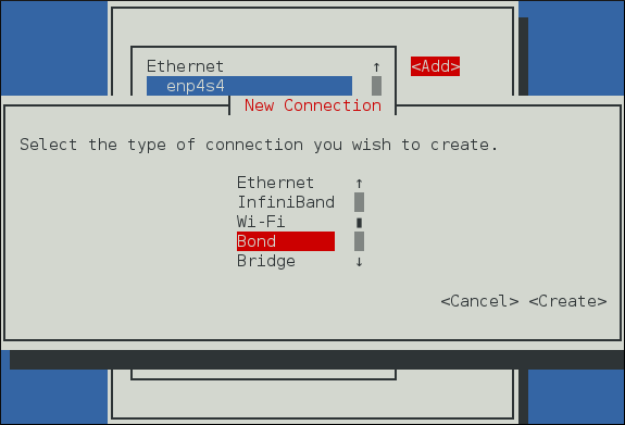
Figure 7.1. The NetworkManager Text User Interface Add a Bond Connection menu
Select
Bond
and then
Create
; the
Edit connection
screen for the bond will open.
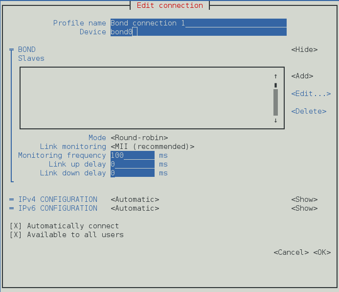
Figure 7.2. The NetworkManager Text User Interface Configuring a Bond Connection menu
At this point port interfaces will need to be added to the bond; to add these select
Add
, the
New Connection
screen opens. Once the type of Connection has been chosen select the
Create
button.
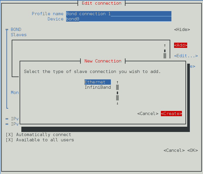
Figure 7.3. The NetworkManager Text User Interface Configuring a New Bond Slave Connection menu
The port's
Edit Connection
display appears; enter the required port's device name or MAC address in the
Device
section. If required, enter a clone MAC address to be used as the bond's MAC address by selecting
Show
to the right of the
Ethernet
label. Select the
OK
button to save the port.
If the device is specified without a MAC address the
Device
section will be automatically populated once the
Edit Connection
window is reloaded, but only if it successfully finds the device.
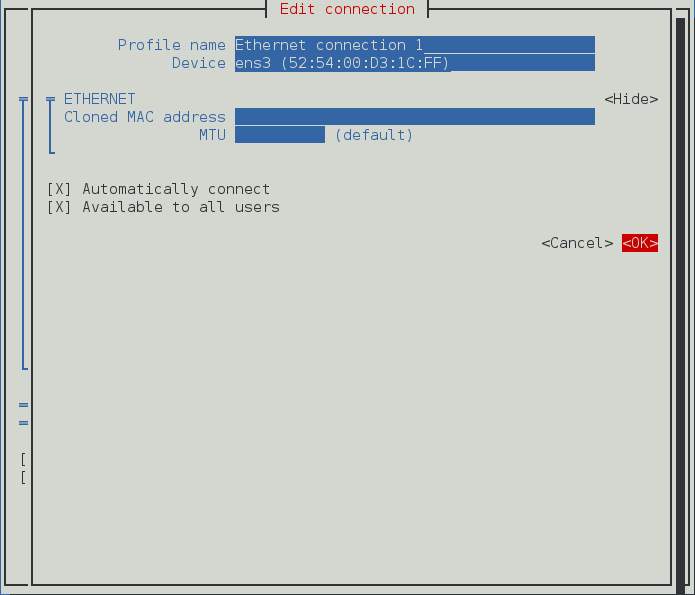
Figure 7.4. The NetworkManager Text User Interface Configuring a Bond Slave Connection menu
The name of the bond port appears in the
Slaves
section. Repeat the above steps to add further port connections.
Review and confirm the settings before selecting the
OK
button.

Figure 7.5. The NetworkManager Text User Interface Completed Bond
See
Section 7.8.1.1, “Configuring the Bond Tab”
for definitions of the bond terms.
See
Section 3.2, “Configuring IP Networking with nmtui”
for information on installing
nmtui
.
7.3. Network Bonding Using the NetworkManager Command Line Tool, nmcli
Note
See
Section 3.3, “Configuring IP Networking with nmcli”
for an introduction to
nmcli
.
To create a
bond
connection with the
nmcli
tool, issue the following command:
~]$ nmcli con add type bond ifname mybond0
Connection 'bond-mybond0' (5f739690-47e8-444b-9620-1895316a28ba) successfully added.
Note that as no
con-name
was given for the bond, the connection name was derived from the interface name by prepending the type.
NetworkManager
supports most of the bonding options provided by the kernel. For example:
~]$ nmcli con add type bond ifname mybond0 bond.options "mode=balance-rr,miimon=100"
Connection 'bond-mybond0' (5f739690-47e8-444b-9620-1895316a28ba) successfully added.
To add a port interface:
Create a new connection, see
Section 3.3.5, “Creating and Modifying a Connection Profile with nmcli”
for details.
Set the controller property to the
bond
interface name, or to the name of the controller connection:
~]$ nmcli con add type ethernet ifname ens3 master mybond0
Connection 'bond-slave-ens3' (220f99c6-ee0a-42a1-820e-454cbabc2618) successfully added.
To add a new
port
interface, repeat the previous command with the new interface. For example:
~]$ nmcli con add type ethernet ifname ens7 master mybond0
Connection 'bond-slave-ens7' (ecc24c75-1c89-401f-90c8-9706531e0231) successfully added.
To activate the ports, issue a command as follows:
~]$ nmcli con up bond-slave-ens7
Connection successfully activated (D-Bus active path: /org/freedesktop/NetworkManager/ActiveConnection/14)
~]$ nmcli con up bond-slave-ens3
Connection successfully activated (D-Bus active path: /org/freedesktop/NetworkManager/ActiveConnection/15)
When you activate a port, the controller connection also starts. You can see
Section 7.1, “Understanding the Default Behavior of Controller and Port Interfaces”
for more information. In this case, it is not necessary to manually activate the controller connection.
It is possible to change the
active_slave
option and the
primary
option of the bond at runtime, without deactivating the connection. For example to change the
active_slave
option, issue the following command:
~]$ nmcli dev mod bond0 +bond.options "active_slave=ens7"
Connection successfully reapplied to device 'bond0'.
or to change the
primary
option:
~]$ nmcli dev mod bond0 +bond.options "primary=ens3"
Connection successfully reapplied to device 'bond0'.
Note
The
active_slave
option sets the currently active port whereas the
primary
option of the bond specifies the active port to be automatically selected by kernel when a new port is added or a failure of the active port occurs.
7.4. Using the Command Line Interface (CLI)
A bond is created using the
bonding
kernel module and a special network interface called a
channel bonding interface
.
7.4.1. Check if Bonding Kernel Module is Installed
In Red Hat Enterprise Linux 7, the bonding module is not loaded by default. You can load the module by issuing the following command as
root
:
~]# modprobe --first-time bonding
This activation will not persist across system restarts. See the
Red Hat Enterprise Linux Kernel Administration Guide
for an explanation of persistent module loading. Note that given a correct configuration file using the
BONDING_OPTS
directive, the bonding module will be loaded as required and therefore does not need to be loaded separately.
To display information about the module, issue the following command:
~]$ modinfo bonding
See the
modprobe(8)
man page for more command options.
7.4.2. Create a Channel Bonding Interface
To create a channel bonding interface, create a file in the
/etc/sysconfig/network-scripts/
directory called
ifcfg-bond
N
, replacing
N
with the number for the interface, such as
0
.
The contents of the file can be based on a configuration file for whatever type of interface is getting bonded, such as an Ethernet interface. The essential differences are that the
DEVICE
directive is
bond
N
, replacing
N
with the number for the interface, and
TYPE=Bond
. In addition, set
BONDING_MASTER=yes
.
Example 7.1. Example ifcfg-bond0 Interface Configuration File
An example of a channel bonding interface.
DEVICE=bond0 NAME=bond0 TYPE=Bond BONDING_MASTER=yes IPADDR=192.168.1.1 PREFIX=24 ONBOOT=yes BOOTPROTO=none BONDING_OPTS="bonding parameters separated by spaces" NM_CONTROLLED="no"
The NAME directive is useful for naming the connection profile in
NetworkManager
. ONBOOT says whether the profile should be started when booting (or more generally, when auto-connecting a device).
Important
Parameters for the bonding kernel module must be specified as a space-separated list in the
BONDING_OPTS="
bonding parameters
"
directive in the
ifcfg-bond
N
interface file. Do
not
specify options for the bonding device in
/etc/modprobe.d/
bonding
.conf
, or in the deprecated
/etc/modprobe.conf
file.
The
max_bonds
parameter is not interface specific and should not be set when using
ifcfg-bond
N
files with the
BONDING_OPTS
directive as this directive will cause the network scripts to create the bond interfaces as required.
For further instructions and advice on configuring the bonding module and to view the list of bonding parameters, see
Section 7.7, “Using Channel Bonding”
.
Note that if the
NM_CONTROLLED="no"
setting is not present, NetworkManager might override settings in this configuration file.
7.4.3. Creating Port Interfaces
The channel bonding interface is the controller (also refered to as
master
) and the interfaces to be bonded are referred to as the ports (
slaves
). After the channel bonding interface is created, the network interfaces to be bound together must be configured by adding the
MASTER
and
SLAVE
directives to the configuration files of the ports. The configuration files for each of the port interfaces can be nearly identical.
Example 7.2. Example Port Interface Configuration File
For example, if two Ethernet interfaces are being channel bonded,
enp1s0
and
enp2s0
, they can both look like the following example:
DEVICE=device_name NAME=bond0-slave TYPE=Ethernet BOOTPROTO=none ONBOOT=yes MASTER=bond0 SLAVE=yes NM_CONTROLLED="no"
In this example, replace
device_name
with the name of the interface. Note that if more than one profile or configuration file exists with
ONBOOT=yes
for an interface, they may race with each other and a plain
TYPE=Ethernet
profile may be activated instead of a bond port.
Note that if the
NM_CONTROLLED="no"
setting is not present, NetworkManager might override settings in this configuration file.
7.4.4. Activating a Channel Bond
To activate a bond, open all the ports. As
root
, issue the following commands:
~]# ifup ifcfg-enp1s0
Connection successfully activated (D-Bus active path: /org/freedesktop/NetworkManager/ActiveConnection/7)
~]# ifup ifcfg-enp2s0
Connection successfully activated (D-Bus active path: /org/freedesktop/NetworkManager/ActiveConnection/8)
Note that if editing interface files for interfaces which are currently
“
up
”
, set them down first as follows:
ifdown device_nameThen when complete, open all the ports, which will open the bond (provided it was not set “ down ” ). To make NetworkManager aware of the changes, issue a command for every changed interface as
root
:
~]# nmcli con load /etc/sysconfig/network-scripts/ifcfg-device
Alternatively, to reload all interfaces:
~]# nmcli con reload
The default behavior is for
NetworkManager
not to be aware of the changes and to continue using the old configuration data. This is set by the
monitor-connection-files
option in the
NetworkManager.conf
file. See the
NetworkManager.conf(5)
manual page for more information.
To view the status of the bond interface, issue the following command:
~]# ip link show
1: lo: <LOOPBACK,UP,LOWER_UP> mtu 65536 qdisc noqueue state UNKNOWN mode DEFAULT
link/loopback 00:00:00:00:00:00 brd 00:00:00:00:00:00
2: enp1s0: <BROADCAST,MULTICAST,SLAVE,UP,LOWER_UP> mtu 1500 qdisc pfifo_fast master bond0 state UP mode DEFAULT qlen 1000
link/ether 52:54:00:e9:ce:d2 brd ff:ff:ff:ff:ff:ff
3: enp2s0: <BROADCAST,MULTICAST,SLAVE,UP,LOWER_UP> mtu 1500 qdisc pfifo_fast master bond0 state UP mode DEFAULT qlen 1000
link/ether 52:54:00:38:a6:4c brd ff:ff:ff:ff:ff:ff
4: bond0: <BROADCAST,MULTICAST,MASTER,UP,LOWER_UP> mtu 1500 qdisc noqueue state UP mode DEFAULT
link/ether 52:54:00:38:a6:4c brd ff:ff:ff:ff:ff:ff
7.4.5. Creating Multiple Bonds
In Red Hat Enterprise Linux, for each bond a channel bonding interface is created including the
BONDING_OPTS
directive. This configuration method is used so that multiple bonding devices can have different configurations. To create multiple channel bonding interfaces, proceed as follows:
Create multiple
ifcfg-bond
N
files with the
BONDING_OPTS
directive; this directive will cause the network scripts to create the bond interfaces as required.
Create, or edit existing, interface configuration files to be bonded and include the
SLAVE
directive.
Assign the interfaces to be bonded, the port interfaces, to the channel bonding interfaces by means of the
MASTER
directive.
Example 7.3. Example multiple ifcfg-bondN interface configuration files
The following is an example of a channel bonding interface configuration file:
DEVICE=bondN NAME=bondN TYPE=Bond BONDING_MASTER=yes IPADDR=192.168.1.1 PREFIX=24 ONBOOT=yes BOOTPROTO=none BONDING_OPTS="bonding parameters separated by spaces"In this example, replace N with the number for the bond interface. For example, to create two bonds create two configuration files,
ifcfg-bond0
and
ifcfg-bond1
, with appropriate
IP
addresses.
Create the interfaces to be bonded as per
Example 7.2, “Example Port Interface Configuration File”
and assign them to the bond interfaces as required using the
MASTER=bond
N
directive. For example, continuing on from the example above, if two interfaces per bond are required, then for two bonds create four interface configuration files and assign the first two using
MASTER=bond
0
and the next two using
MASTER=bond
1
.
7.5. Verifying Network Configuration Bonding for Redundancy
Network redundancy is a process when devices are used for backup purposes to prevent or recover from a failure of a specific system. The following procedure describes how to verify the network configuration for bonding in redundancy:
Procedure
Ping the destination IP from the bond interface. For example:
~]# ping -I bond0 DSTADDR
View which interface is in
active
mode:
~]# cat /sys/class/net/bond0/bonding/active_slave
enp1s0
enp1s0
is the
active
port interface.
Set the
active
port interface down:
~]# ip link set enp1s0 down
Check if the
backup
interface is up:
~]# cat /sys/class/net/bond0/bonding/active_slave
enp2s0
enp2s0
is now the
active
port interface.
Check if you can still ping the destination IP from the bond interface:
~]# ping -I bond0 DSTADDR
7.6. Overview of Bonding Modes and the Required Settings on the Switch
The following table describes the required configuration that you must apply to the upstream switch depending on the bonding mode:
Table 7.1. Switch Configuration Settings Depending on the Bonding Modes
| Bonding Mode | Configuration on the Switch |
|---|---|
0
-
balance-rr
|
Requires static Etherchannel enabled (not LACP-negotiated) |
1
-
active-backup
|
Requires autonomous ports |
2
-
balance-xor
|
Requires static Etherchannel enabled (not LACP-negotiated) |
3
-
broadcast
|
Requires static Etherchannel enabled (not LACP-negotiated) |
4
-
802.3ad
|
Requires LACP-negotiated Etherchannel enabled |
5
-
balance-tlb
|
Requires autonomous ports |
6
-
balance-alb
|
Requires autonomous ports |
For configuring these settings on your switch, see the switch documentation.
7.7. Using Channel Bonding
To enhance performance, adjust available module options to ascertain what combination works best. Pay particular attention to the
miimon
or
arp_interval
and the
arp_ip_target
parameters. See
Section 7.7.1, “Bonding Module Directives”
for a list of available options and how to quickly determine the best ones for your bonded interface.
7.7.1. Bonding Module Directives
It is a good idea to test which channel bonding module parameters work best for your bonded interfaces before adding them to the
BONDING_OPTS="
bonding parameters
"
directive in your bonding interface configuration file (
ifcfg-bond0
for example). Parameters to bonded interfaces can be configured without unloading (and reloading) the bonding module by manipulating files in the
sysfs
file system.
sysfs
is a virtual file system that represents kernel objects as directories, files and symbolic links.
sysfs
can be used to query for information about kernel objects, and can also manipulate those objects through the use of normal file system commands. The
sysfs
virtual file system is mounted under the
/sys/
directory. All bonding interfaces can be configured dynamically by interacting with and manipulating files under the
/sys/class/net/
directory.
In order to determine the best parameters for your bonding interface, create a channel bonding interface file such as
ifcfg-bond0
by following the instructions in
Section 7.4.2, “Create a Channel Bonding Interface”
. Insert the
SLAVE=yes
and
MASTER=bond0
directives in the configuration files for each interface bonded to
bond0
. Once this is completed, you can proceed to testing the parameters.
First, open the bond you created by running
ifup
bond
N
as
root
:
~]# ifup bond0
If you have correctly created the
ifcfg-bond0
bonding interface file, you will be able to see
bond0
listed in the output of running
ip link show
as
root
:
~]# ip link show
1: lo: <LOOPBACK,UP,LOWER_UP> mtu 65536 qdisc noqueue state UNKNOWN mode DEFAULT
link/loopback 00:00:00:00:00:00 brd 00:00:00:00:00:00
2: enp1s0: <BROADCAST,MULTICAST,SLAVE,UP,LOWER_UP> mtu 1500 qdisc pfifo_fast master bond0 state UP mode DEFAULT qlen 1000
link/ether 52:54:00:e9:ce:d2 brd ff:ff:ff:ff:ff:ff
3: enp2s0: <BROADCAST,MULTICAST,SLAVE,UP,LOWER_UP> mtu 1500 qdisc pfifo_fast master bond0 state UP mode DEFAULT qlen 1000
link/ether 52:54:00:38:a6:4c brd ff:ff:ff:ff:ff:ff
4: bond0: <BROADCAST,MULTICAST,MASTER,UP,LOWER_UP> mtu 1500 qdisc noqueue state UP mode DEFAULT
link/ether 52:54:00:38:a6:4c brd ff:ff:ff:ff:ff:ff
To view all existing bonds, even if they are not up, run:
~]$ cat /sys/class/net/bonding_masters
bond0
You can configure each bond individually by manipulating the files located in the
/sys/class/net/bond
N
/bonding/
directory. First, the bond you are configuring must be taken down:
~]# ifdown bond0
As an example, to enable MII monitoring on bond0 with a 1 second interval, run as
root
:
~]# echo 1000 > /sys/class/net/bond0/bonding/miimon
To configure bond0 for
balance-alb
mode, run either:
~]# echo 6 > /sys/class/net/bond0/bonding/mode
...or, using the name of the mode:
~]# echo balance-alb > /sys/class/net/bond0/bonding/mode
After configuring options for the bond in question, you can bring it up and test it by running
ifup bond
N
. If you decide to change the options, take the interface down, modify its parameters using
sysfs
, bring it back up, and re-test.
Once you have determined the best set of parameters for your bond, add those parameters as a space-separated list to the
BONDING_OPTS=
directive of the
/etc/sysconfig/network-scripts/ifcfg-bond
N
file for the bonding interface you are configuring. Whenever that bond is brought up (for example, by the system during the boot sequence if the
ONBOOT=yes
directive is set), the bonding options specified in the
BONDING_OPTS
will take effect for that bond.
The following list provides the names of many of the more common channel bonding parameters, along with a description of what they do. For more information, see the brief descriptions for each
parm
in
modinfo bonding
output, or for more detailed information, see
https://www.kernel.org/doc/Documentation/networking/bonding.txt
.
Bonding Interface Parameters
-
ad_select= value -
Specifies the 802.3ad aggregation selection logic to use. Possible values are:
stableor0— Default setting. The active aggregator is chosen by largest aggregate bandwidth. Reselection of the active aggregator occurs only when all ports of the active aggregator are down or if the active aggregator has no ports.bandwidthor1— The active aggregator is chosen by largest aggregate bandwidth. Reselection occurs if: A port is added to or removed from the bond; Any port's link state changes; Any port's 802.3ad association state changes; The bond's administrative state changes to up.countor2— The active aggregator is chosen by the largest number of ports. Reselection occurs as described for thebandwidthsetting above. Thebandwidthandcountselection policies permit failover of 802.3ad aggregations when partial failure of the active aggregator occurs. This keeps the aggregator with the highest availability, either in bandwidth or in number of ports, active at all times. -
arp_interval= time_in_milliseconds -
Specifies, in milliseconds, how often
ARPmonitoring occurs.Important
It is essential that botharp_intervalandarp_ip_targetparameters are specified, or, alternatively, themiimonparameter is specified. Failure to do so can cause degradation of network performance in the event that a link fails. If using this setting while inmode=0ormode=2(the two load-balancing modes), the network switch must be configured to distribute packets evenly across the NICs. For more information on how to accomplish this, see https://www.kernel.org/doc/Documentation/networking/bonding.txt . The value is set to0by default, which disables it. -
arp_ip_target= ip_address [ , ip_address_2 ,… ip_address_16 ] -
Specifies the target
IPaddress ofARPrequests when thearp_intervalparameter is enabled. Up to 16IPaddresses can be specified in a comma separated list. -
arp_validate= value -
Validate source/distribution of
ARPprobes; default isnone. Other valid values areactive,backup, andall. -
downdelay= time_in_milliseconds -
Specifies (in milliseconds) how long to wait after link failure before disabling the link. The value must be a multiple of the value specified in the
miimonparameter. The value is set to0by default, which disables it. -
fail_over_mac= value -
Specifies whether active-backup mode should set all ports to the same MAC address at the point of assignment (the traditional behavior), or, when enabled, perform special handling of the bond's MAC address in accordance with the selected policy. Possible values are:
noneor0— Default setting. This setting disablesfail_over_mac, and causes bonding to set all ports of an active-backup bond to the same MAC address at the point of assignment.activeor1— The “ active ”fail_over_macpolicy indicates that the MAC address of the bond should always be the MAC address of the currently active port. The MAC address of the ports is not changed; instead, the MAC address of the bond changes during a failover. This policy is useful for devices that cannot ever alter their MAC address, or for devices that refuse incoming broadcasts with their own source MAC (which interferes with the ARP monitor). The disadvantage of this policy is that every device on the network must be updated by gratuitous ARP, as opposed to the normal method of switches snooping incoming traffic to update their ARP tables. If the gratuitous ARP is lost, communication may be disrupted. When this policy is used in conjunction with the MII monitor, devices which assert link up prior to being able to actually transmit and receive are particularly susceptible to loss of the gratuitous ARP, and an appropriate updelay setting may be required.followor2— The “ follow ”fail_over_macpolicy causes the MAC address of the bond to be selected normally (normally the MAC address of the first port added to the bond). However, the second and subsequent ports are not set to this MAC address while they are in a backup role; a port is programmed with the bond's MAC address at failover time (and the formerly active port receives the newly active port's MAC address). This policy is useful for multiport devices that either become confused or incur a performance penalty when multiple ports are programmed with the same MAC address. - lacp_rate= value
-
Specifies the rate at which link partners should transmit LACPDU packets in 802.3ad mode. Possible values are:
slowor0— Default setting. This specifies that partners should transmit LACPDUs every 30 seconds.fastor1— Specifies that partners should transmit LACPDUs every 1 second.
miimon=
time_in_milliseconds
Specifies (in milliseconds) how often MII link monitoring occurs. This is useful if high availability is required because MII is used to verify that the NIC is active. To verify that the driver for a particular NIC supports the MII tool, type the following command as root:
~]# ethtool interface_name | grep "Link detected:"
In this command, replace
interface_name
with the name of the device interface, such as
enp1s0
, not the bond interface. If MII is supported, the command returns:
Link detected: yes
If using a bonded interface for high availability, the module for each NIC must support MII. Setting the value to
0
(the default), turns this feature off. When configuring this setting, a good starting point for this parameter is
100
.
Important
It is essential that both
arp_interval
and
arp_ip_target
parameters are specified, or, alternatively, the
miimon
parameter is specified. Failure to do so can cause degradation of network performance in the event that a link fails.
mode=
value
Allows you to specify the bonding policy. The
value
can be one of:
balance-rr
or
0
— Sets a round-robin policy for fault tolerance and load balancing. Transmissions are received and sent out sequentially on each bonded port interface beginning with the first one available.
active-backup
or
1
— Sets an active-backup policy for fault tolerance. Transmissions are received and sent out through the first available bonded port interface. Another bonded port interface is only used if the active bonded port interface fails.
balance-xor
or
2
— Transmissions are based on the selected hash policy. The default is to derive a hash by XOR of the source and destination MAC addresses multiplied by the modulo of the number of port interfaces. In this mode traffic destined for specific peers will always be sent over the same interface. As the destination is determined by the MAC addresses this method works best for traffic to peers on the same link or local network. If traffic has to pass through a single router then this mode of traffic balancing will be suboptimal.
broadcast
or
3
— Sets a broadcast policy for fault tolerance. All transmissions are sent on all port interfaces.
802.3ad
or
4
— Sets an IEEE 802.3ad dynamic link aggregation policy. Creates aggregation groups that share the same speed and duplex settings. Transmits and receives on all ports in the active aggregator. Requires a switch that is 802.3ad compliant.
balance-tlb
or
5
— Sets a Transmit Load Balancing (TLB) policy for fault tolerance and load balancing. The outgoing traffic is distributed according to the current load on each port interface. Incoming traffic is received by the current port. If the receiving port fails, another port takes over the MAC address of the failed port. This mode is only suitable for local addresses known to the kernel bonding module and therefore cannot be used behind a bridge with virtual machines.
balance-alb
or
6
— Sets an Adaptive Load Balancing (ALB) policy for fault tolerance and load balancing. Includes transmit and receive load balancing for
IPv4
traffic. Receive load balancing is achieved through
ARP
negotiation. This mode is only suitable for local addresses known to the kernel bonding module and therefore cannot be used behind a bridge with virtual machines.
For details about required settings on the upstream switch, see
Section 7.6, “Overview of Bonding Modes and the Required Settings on the Switch”
.
primary=
interface_name
Specifies the interface name, such as
enp1s0
, of the primary device. The
primary
device is the first of the bonding interfaces to be used and is not abandoned unless it fails. This setting is particularly useful when one NIC in the bonding interface is faster and, therefore, able to handle a bigger load.
This setting is only valid when the bonding interface is in
active-backup
mode. See
https://www.kernel.org/doc/Documentation/networking/bonding.txt
for more information.
primary_reselect=
value
Specifies the reselection policy for the primary port. This affects how the primary port is chosen to become the active port when failure of the active port or recovery of the primary port occurs. This parameter is designed to prevent flip-flopping between the primary port and other ports. Possible values are:
always
or
0
(default) — The primary port becomes the active port whenever it comes back up.
better
or
1
— The primary port becomes the active port when it comes back up, if the speed and duplex of the primary port is better than the speed and duplex of the current active port.
failure
or
2
— The primary port becomes the active port only if the current active port fails and the primary port is up.
The
primary_reselect
setting is ignored in two cases:
If no ports are active, the first port to recover is made the active port.
When initially assigned to a bond, the primary port is always made the active port.
Changing the
primary_reselect
policy through
sysfs
will cause an immediate selection of the best active port according to the new policy. This may or may not result in a change of the active port, depending upon the circumstances
resend_igmp=
range
Specifies the number of IGMP membership reports to be issued after a failover event. One membership report is issued immediately after the failover, subsequent packets are sent in each 200ms interval.
The valid range is
0
to
255
; the default value is
1
. A value of
0
prevents the IGMP membership report from being issued in response to the failover event.
This option is useful for bonding modes
balance-rr
(mode 0),
active-backup
(mode 1),
balance-tlb
(mode 5) and
balance-alb
(mode 6), in which a failover can switch the IGMP traffic from one port to another. Therefore a fresh IGMP report must be issued to cause the switch to forward the incoming IGMP traffic over the newly selected port.
updelay=
time_in_milliseconds
Specifies (in milliseconds) how long to wait before enabling a link. The value must be a multiple of the value specified in the
miimon
parameter. The value is set to
0
by default, which disables it.
use_carrier=
number
Specifies whether or not
miimon
should use MII/ETHTOOL ioctls or
netif_carrier_ok()
to determine the link state. The
netif_carrier_ok()
function relies on the device driver to maintains its state with
netif_carrier_
on/off
; most device drivers support this function.
The MII/ETHTOOL ioctls tools utilize a deprecated calling sequence within the kernel. However, this is still configurable in case your device driver does not support
netif_carrier_
on/off
.
Valid values are:
1
— Default setting. Enables the use of
netif_carrier_ok()
.
0
— Enables the use of MII/ETHTOOL ioctls.
If the bonding interface insists that the link is up when it should not be, it is possible that your network device driver does not support
netif_carrier_
on/off
.
xmit_hash_policy=
value
Selects the transmit hash policy used for port selection in
balance-xor
and
802.3ad
modes. Possible values are:
0
or
layer2
— Default setting. This parameter uses the XOR of hardware MAC addresses to generate the hash. The formula used is:
(source_MAC_address XOR destination_MAC) MODULO slave_count
This algorithm will place all traffic to a particular network peer on the same port, and is 802.3ad compliant.
1
or
layer3+4
— Uses upper layer protocol information (when available) to generate the hash. This allows for traffic to a particular network peer to span multiple ports, although a single connection will not span multiple ports.
The formula for unfragmented TCP and UDP packets used is:
((source_port XOR dest_port) XOR
((source_IP XOR dest_IP) AND 0xffff)
MODULO slave_count
For fragmented TCP or UDP packets and all other
IP
protocol traffic, the source and destination port information is omitted. For non-
IP
traffic, the formula is the same as the
layer2
transmit hash policy.
This policy intends to mimic the behavior of certain switches; particularly, Cisco switches with PFC2 as well as some Foundry and IBM products.
The algorithm used by this policy is not 802.3ad compliant.
2
or
layer2+3
— Uses a combination of layer2 and layer3 protocol information to generate the hash.
Uses XOR of hardware MAC addresses and
IP
addresses to generate the hash. The formula is:
(((source_IP XOR dest_IP) AND 0xffff) XOR
( source_MAC XOR destination_MAC ))
MODULO slave_count
This algorithm will place all traffic to a particular network peer on the same port. For non-
IP
traffic, the formula is the same as for the layer2 transmit hash policy.
This policy is intended to provide a more balanced distribution of traffic than layer2 alone, especially in environments where a layer3 gateway device is required to reach most destinations.
This algorithm is 802.3ad compliant.
7.8. Creating a Bond Connection Using a GUI
You can use the GNOME
control-center
utility to direct
NetworkManager
to create a Bond from two or more Wired or InfiniBand connections. It is not necessary to create the connections to be bonded first. They can be configured as part of the process to configure the bond. You must have the MAC addresses of the interfaces available in order to complete the configuration process.
7.8.1. Establishing a Bond Connection
Procedure 7.1. Adding a New Bond Connection_Using nm-connection-editor
Follow the below steps to create a new bond connection.
Enter
nm-connection-editor
in a terminal:
~]$ nm-connection-editor
Click the
Add
button. The
Choose a Connection Type
window appears. Select
Bond
and click
Create
. The
Editing Bond connection
1
window appears.
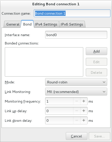
Figure 7.6. The NetworkManager Graphical User Interface Add a Bond menu
On the
Bond
tab, click
Add
and select the type of interface you want to use with the bond connection. Click the
Create
button. Note that the dialog to select the port type only comes up when you create the first port; after that, it will automatically use that same type for all further ports.
The
Editing bond0 slave 1
window appears. Use the
Device MAC address
drop-down menu to select the MAC address of the interface to be bonded. The first port's MAC address will be used as the MAC address for the bond interface. If required, enter a clone MAC address to be used as the bond's MAC address. Click the
Save
button.
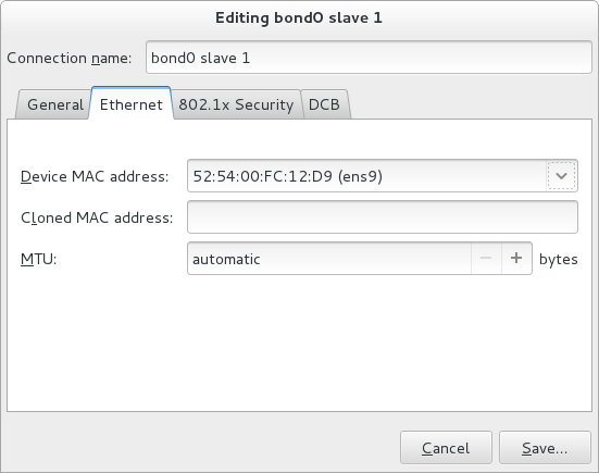
Figure 7.7. The NetworkManager Graphical User Interface Add a Bond Connection menu
The name of the bonded port appears in the
Bonded connections
window. Click the
Add
button to add further port connections.
Review and confirm the settings and then click the
Save
button.
Edit the bond-specific settings by referring to
Section 7.8.1.1, “Configuring the Bond Tab”
below.
Procedure 7.2. Editing an Existing Bond Connection
Follow these steps to edit an existing bond connection.
Enter
nm-connection-editor
in a terminal:
~]$ nm-connection-editor
Select the connection you want to edit and click the
Edit
button.
Select the
General
tab.
Configure the connection name, auto-connect behavior, and availability settings.
Five settings in the
Editing
dialog are common to all connection types, see the
General
tab:
Connection name
— Enter a descriptive name for your network connection. This name will be used to list this connection in the menu of the
Network
window.
Automatically connect to this network when it is available
— Select this box if you want
NetworkManager
to auto-connect to this connection when it is available. See
the section called “Editing an Existing Connection with control-center”
for more information.
All users may connect to this network
— Select this box to create a connection available to all users on the system. Changing this setting may require root privileges. See
Section 3.4.5, “Managing System-wide and Private Connection Profiles with a GUI”
for details.
Automatically connect to VPN when using this connection
— Select this box if you want
NetworkManager
to auto-connect to a VPN connection when it is available. Select the VPN from the drop-down menu.
Firewall Zone
— Select the firewall zone from the drop-down menu. See the
Red Hat Enterprise Linux 7 Security Guide
for more information on firewall zones.
Edit the bond-specific settings by referring to
Section 7.8.1.1, “Configuring the Bond Tab”
below.
Saving Your New (or Modified) Connection and Making Further Configurations
Once you have finished editing your bond connection, click the
Save
button to save your customized configuration.
Then, to configure:
IPv4
settings for the connection, click the
IPv4 Settings
tab and proceed to
Section 5.4, “Configuring IPv4 Settings”
IPv6
settings for the connection, click the
IPv6 Settings
tab and proceed to
Section 5.5, “Configuring IPv6 Settings”
.
7.8.1.1. Configuring the Bond Tab
If you have already added a new bond connection (see
Procedure 7.1, “Adding a New Bond Connection_Using nm-connection-editor”
for instructions), you can edit the
Bond
tab to set the load sharing mode and the type of link monitoring to use to detect failures of a port connection.
The mode that is used to share traffic over the port connections which make up the bond. The default is
Round-robin
. Other load sharing modes, such as
802.3ad
, can be selected by means of the drop-down list.
The method of monitoring the ports ability to carry network traffic.
The following modes of load sharing are selectable from the
Mode
drop-down list:
- Round-robin
-
Sets a round-robin policy for fault tolerance and load balancing. Transmissions are received and sent out sequentially on each bonded port interface beginning with the first one available. This mode might not work behind a bridge with virtual machines without additional switch configuration.
- Active backup
-
Sets an active-backup policy for fault tolerance. Transmissions are received and sent out through the first available bonded port interface. Another bonded port interface is only used if the active bonded port interface fails. Note that this is the only mode available for bonds of InfiniBand devices. Sets an XOR (exclusive-or) policy. Transmissions are based on the selected hash policy. The default is to derive a hash by XOR of the source and destination MAC addresses multiplied by the modulo of the number of port interfaces. In this mode traffic destined for specific peers will always be sent over the same interface. As the destination is determined by the MAC addresses this method works best for traffic to peers on the same link or local network. If traffic has to pass through a single router then this mode of traffic balancing will be suboptimal.
- Broadcast
-
Sets a broadcast policy for fault tolerance. All transmissions are sent on all port interfaces. This mode might not work behind a bridge with virtual machines without additional switch configuration.
- 802.3ad
-
Sets an IEEE
802.3addynamic link aggregation policy. Creates aggregation groups that share the same speed and duplex settings. Transmits and receives on all ports in the active aggregator. Requires a network switch that is802.3adcompliant. - Adaptive transmit load balancing
-
Sets an adaptive Transmit Load Balancing (TLB) policy for fault tolerance and load balancing. The outgoing traffic is distributed according to the current load on each port interface. Incoming traffic is received by the current port. If the receiving port fails, another port takes over the MAC address of the failed port. This mode is only suitable for local addresses known to the kernel bonding module and therefore cannot be used behind a bridge with virtual machines.
- Adaptive load balancing
-
Sets an Adaptive Load Balancing (ALB) policy for fault tolerance and load balancing. Includes transmit and receive load balancing for
IPv4traffic. Receive load balancing is achieved throughARPnegotiation. This mode is only suitable for local addresses known to the kernel bonding module and therefore cannot be used behind a bridge with virtual machines. The following types of link monitoring can be selected from the Link Monitoring drop-down list. It is a good idea to test which channel bonding module parameters work best for your bonded interfaces.- MII (Media Independent Interface)
-
The state of the carrier wave of the interface is monitored. This can be done by querying the driver, by querying MII registers directly, or by using ethtool to query the device. Three options are available:
- Monitoring Frequency
-
The time interval, in milliseconds, between querying the driver or MII registers.
- Link up delay
-
The time in milliseconds to wait before attempting to use a link that has been reported as up. This delay can be used if some gratuitous
ARPrequests are lost in the period immediately following the link being reported as “ up ” . This can happen during switch initialization for example. - Link down delay
-
The time in milliseconds to wait before changing to another link when a previously active link has been reported as “ down ” . This delay can be used if an attached switch takes a relatively long time to change to backup mode. The address resolution protocol (
ARP) is used to probe one or more peers to determine how well the link-layer connections are working. It is dependent on the device driver providing the transmit start time and the last receive time. Two options are available:- Monitoring Frequency
-
The time interval, in milliseconds, between sending
ARPrequests. - ARP targets
-
A comma separated list of
IPaddresses to sendARPrequests to.
7.9. Additional Resources
Installed Documentation
-
nmcli(1)man page — Describes NetworkManager 's command‐line tool.nmcli-examples(5)man page — Gives examples of nmcli commands.nm-settings(5)man page — Description of settings and parameters of NetworkManager connections.
Online Documentation
- Red Hat Enterprise Linux System Administrator's Guide
-
Explains the use of kernel module capabilities.
- https://access.redhat.com/site/node/28421/Configuring_VLAN_devices_over_a_bonded_interface
-
A Red Hat Knowledgebase article about Configuring VLAN devices over a bonded interface.
Chapter 8. Configure Network Teaming
8.1. Understanding Network Teaming
The combining or aggregating of network links to provide a logical link with higher throughput, or to provide redundancy, is known by many names, for example
channel bonding
,
Ethernet bonding
,
port trunking
,
channel teaming
,
NIC teaming
, or
link aggregation
. This concept as originally implemented in the Linux kernel is widely referred to as
bonding
. The term
Network Teaming
has been chosen to refer to this new implementation of the concept. The existing bonding driver is unaffected, Network Teaming is offered as an alternative and does not replace bonding in Red Hat Enterprise Linux 7.
Regarding the Mode 4 Link Aggregation Control Protocol (LACP) teaming mode, requires configuring the switch to aggregate the links. For more details, see
https://www.kernel.org/doc/Documentation/networking/bonding.txt
Network Teaming, or Team, is designed to implement the concept in a different way by providing a small kernel driver to implement the fast handling of packet flows, and various user-space applications to do everything else in user space. The driver has an
Application Programming Interface
(
API
), referred to as
“
Team Netlink API
”
, which implements Netlink communications. User-space applications can use this API to communicate with the driver. A library, referred to as
“
lib
”
, has been provided to do user space wrapping of Team Netlink communications and RT Netlink messages. An application daemon,
teamd
, which uses the
libteam
library is also available. One instance of
teamd
can control one instance of the Team driver. The daemon implements the load-balancing and active-backup logic, such as round-robin, by using additional code referred to as
“
runners
”
. By separating the code in this way, the Network Teaming implementation presents an easily extensible and scalable solution for load-balancing and redundancy requirements. For example, custom runners can be relatively easily written to implement new logic through
teamd
, and even
teamd
is optional, users can write their own application to use
libteam
.
The
teamdctl
utility is available to control a running instance of
teamd
using D-bus.
teamdctl
provides a D-Bus wrapper around the
teamd
D-Bus API. By default,
teamd
listens and communicates using Unix Domain Sockets but still monitors D-Bus. This is to ensure that
teamd
can be used in environments where D-Bus is not present or not yet loaded. For example, when booting over
teamd
links, D-Bus would not yet be loaded. The
teamdctl
utility can be used during run time to read the configuration, the state of link-watchers, check and change the state of ports, add and remove ports, and to change ports between active and backup states.
Team Netlink API communicates with user-space applications using Netlink messages. The
libteam
user-space library does not directly interact with the API, but uses
libnl
or
teamnl
to interact with the driver API.
To sum up, the instances of Team driver, running in the kernel, do not get configured or controlled directly. All configuration is done with the aid of user space applications, such as the
teamd
application. The application then directs the kernel driver part accordingly.
In the context of network teaming, the term
port
is also known as
slave
.
Port
is preferred when using
teamd
directly while
slave
is used when using
NetworkManager
to refer to interfaces which create a team.
8.2. Understanding the Default Behavior of Controller and Port Interfaces
When controlling teamed port interfaces using the
NetworkManager
daemon, and especially when fault finding, keep the following in mind:
Starting the controller interface does not automatically start the port interfaces.
Starting a port interface always starts the controller interface.
Stopping the controller interface also stops the port interfaces.
A controller without ports can start static
IP
connections.
A controller without ports waits for ports when starting
DHCP
connections.
A controller with a
DHCP
connection waiting for ports completes when a port with a carrier is added.
A controller with a
DHCP
connection waiting for ports continues waiting when a port without a carrier is added.
Warning
The use of direct cable connections without network switches is not supported for teaming. The failover mechanisms described here will not work as expected without the presence of network switches. See the Red Hat Knowledgebase article
Why is bonding not supported with direct connection using crossover cables?
for more information.
8.3. Comparison of Network Teaming to Bonding
Table 8.1. A Comparison of Features in Bonding and Team
| Feature | Bonding | Team |
|---|---|---|
| broadcast Tx policy | Yes | Yes |
| round-robin Tx policy | Yes | Yes |
| active-backup Tx policy | Yes | Yes |
| LACP (802.3ad) support | Yes (active only) | Yes |
| Hash-based Tx policy | Yes | Yes |
| User can set hash function | No | Yes |
| Tx load-balancing support (TLB) | Yes | Yes |
| LACP hash port select | Yes | Yes |
| load-balancing for LACP support | No | Yes |
| Ethtool link monitoring | Yes | Yes |
| ARP link monitoring | Yes | Yes |
| NS/NA (IPv6) link monitoring | No | Yes |
| ports up/down delays | Yes | Yes |
| port priorities and stickiness ( “ primary ” option enhancement) | No | Yes |
| separate per-port link monitoring setup | No | Yes |
| multiple link monitoring setup | Limited | Yes |
| lockless Tx/Rx path | No (rwlock) | Yes (RCU) |
| VLAN support | Yes | Yes |
| user-space runtime control | Limited | Full |
| Logic in user-space | No | Yes |
| Extensibility | Hard | Easy |
| Modular design | No | Yes |
| Performance overhead | Low | Very Low |
| D-Bus interface | No | Yes |
| multiple device stacking | Yes | Yes |
| zero config using LLDP | No | (in planning) |
| NetworkManager support | Yes | Yes |
8.4. Understanding the Network Teaming Daemon and the "Runners"
The Team daemon,
teamd
, uses
libteam
to control one instance of the team driver. This instance of the team driver adds instances of a hardware device driver to form a
“
team
”
of network links. The team driver presents a network interface,
team0
for example, to the other parts of the kernel. The interfaces created by instances of the team driver are given names such as
team0
,
team1
, and so forth in the documentation. This is for ease of understanding and other names can be used. The logic common to all methods of teaming is implemented by
teamd
; those functions that are unique to the different load sharing and backup methods, such as round-robin, are implemented by separate units of code referred to as
“
runners
”
. Because words such as
“
module
”
and
“
mode
”
already have specific meanings in relation to the kernel, the word
“
runner
”
was chosen to refer to these units of code. The user specifies the runner in the JSON format configuration file and the code is then compiled into an instance of
teamd
when the instance is created. A runner is not a plug-in because the code for a runner is compiled into an instance of
teamd
as it is being created. Code could be created as a plug-in for
teamd
should the need arise.
The following runners are available at time of writing.
broadcast (data is transmitted over all ports)
round-robin (data is transmitted over all ports in turn)
active-backup (one port or link is used while others are kept as a backup)
loadbalance (with active Tx load balancing and BPF-based Tx port selectors)
lacp (implements the 802.3ad Link Aggregation Control Protocol)
In addition, the following link-watchers are available:
ethtool
(Libteam lib uses
ethtool
to watch for link state changes). This is the default if no other link-watcher is specified in the configuration file.
arp_ping
(The
arp_ping
utility is used to monitor the presence of a far-end hardware address using ARP packets.)
nsna_ping
(Neighbor Advertisements and Neighbor Solicitation from the
IPv6
Neighbor Discovery protocol are used to monitor the presence of a neighbor's interface)
There are no restrictions in the code to prevent a particular link-watcher from being used with a particular runner, however when using the
lacp
runner,
ethtool
is the only recommended link-watcher.
8.5. Install the Network Teaming Daemon
The networking teaming daemon,
teamd
, is not installed by default. To install
teamd
, issue the following command as
root
:
~]# yum install teamd
8.6. Converting a Bond to a Team
It is possible to convert existing bonding configuration files to team configuration files using the
bond2team
tool. It can convert bond configuration files in
ifcfg
format to team configuration files in either
ifcfg
or JSON format. Note that firewall rules, alias interfaces, and anything that might be tied to the original interface name can break after the renaming because the tool will only change the
ifcfg
file, nothing else.
To see some examples of the command format, issue the following command:
~]$ bond2team --examples
New files will be created in a directory whose name starts with
/tmp/bond2team.XXXXXX/
, where XXXXXX is a random string. After creating the new configuration files, move the old bonding files to a backup folder and then move the new files to the
/etc/sysconfig/network-scripts/
directory.
Example 8.1. Convert a Bond to a Team
To convert a current
bond0
configuration to team
ifcfg
, issue a command as
root
:
~]# /usr/bin/bond2team --master bond0
Note that this will retain the name
bond0
. To use a new name to save the configuration, use the
--rename
as follows:
~]# /usr/bin/bond2team --master bond0 --rename team0
add the
--json
option to output JSON format files instead of
ifcfg
files. See the
teamd.conf(5)
man page for examples of JSON format.
Example 8.2. Convert a Bond to a Team and Specify the File Path
To convert a current
bond0
configuration to team
ifcfg
, and to manually specify the path to the
ifcfg
file, issue a command as
root
:
~]# /usr/bin/bond2team --master bond0 --configdir /path/to/ifcfg-file
add the
--json
option to output JSON format files instead of
ifcfg
files.
Example 8.3. Create a Team Configuration Using Bond2team
It is also possible to create a team configuration by supplying the
bond2team
tool with a list of bonding parameters. For example:
~]# /usr/bin/bond2team --bonding_opts "mode=1 miimon=500"
Ports can also be supplied on the command line as follows:
~]#See the/usr/bin/bond2team --bonding_opts "mode=1 miimon=500 primary=enp1s0 \primary_reselect-0" --port enp1s0 --port enp2s0 --port enp3s0 --port enp4s0
bond2team(1)
man page for further details. For an explanation of bonding parameters, see
Section 7.7, “Using Channel Bonding”
8.7. Selecting Interfaces to Use as Ports for a Network Team
To view the available interfaces, issue the following command:
~]$ ip link show
1: lo: <LOOPBACK,UP,LOWER_UP > mtu 65536 qdisc noqueue state UNKNOWN mode DEFAULT
link/loopback 00:00:00:00:00:00 brd 00:00:00:00:00:00
2: em1: <BROADCAST,MULTICAST,UP,LOWER_UP > mtu 1500 qdisc pfifo_fast state UP mode DEFAULT qlen 1000
link/ether 52:54:00:6a:02:8a brd ff:ff:ff:ff:ff:ff
3: em2: <BROADCAST,MULTICAST,UP,LOWER_UP > mtu 1500 qdisc pfifo_fast state UP mode DEFAULT qlen 1000
link/ether 52:54:00:9b:6d:2a brd ff:ff:ff:ff:ff:ff
From the available interfaces, determine which are suitable for adding to your network team and then proceed to
Section 8.8, “Selecting Network Team Configuration Methods”
8.8. Selecting Network Team Configuration Methods
To configure a network team using
NetworkManager
's text user interface tool,
nmtui
, proceed to
Section 8.9, “Configure a Network Team Using the Text User Interface, nmtui”
To create a network team using the command-line tool
,
nmcli
, proceed to
Section 8.10.1, “Configure Network Teaming Using nmcli”
.
To create a network team using the Team daemon
,
teamd
, proceed to
Section 8.10.2, “Creating a Network Team Using teamd”
.
To create a network team using configuration files
, proceed to
Section 8.10.3, “Creating a Network Team Using ifcfg Files”
.
To configure a network team using a graphical user interface
, see
Section 8.14, “Creating a Network Team Using a GUI”
8.9. Configure a Network Team Using the Text User Interface, nmtui
The text user interface tool
nmtui
can be used to configure teaming in a terminal window. Issue the following command to start the tool:
~]$ nmtui
The text user interface appears. Any invalid command prints a usage message.
To navigate, use the arrow keys or press
Tab
to step forwards and press
Shift
+
Tab
to step back through the options. Press
Enter
to select an option. The
Space
bar toggles the status of a check box.
From the starting menu, select
Edit a connection
. Select
Add
, the
New Connection
screen opens.
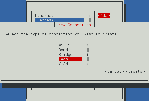
Figure 8.1. The NetworkManager Text User Interface Add a Team Connection menu
Select
Team
, the
Edit connection
screen opens.
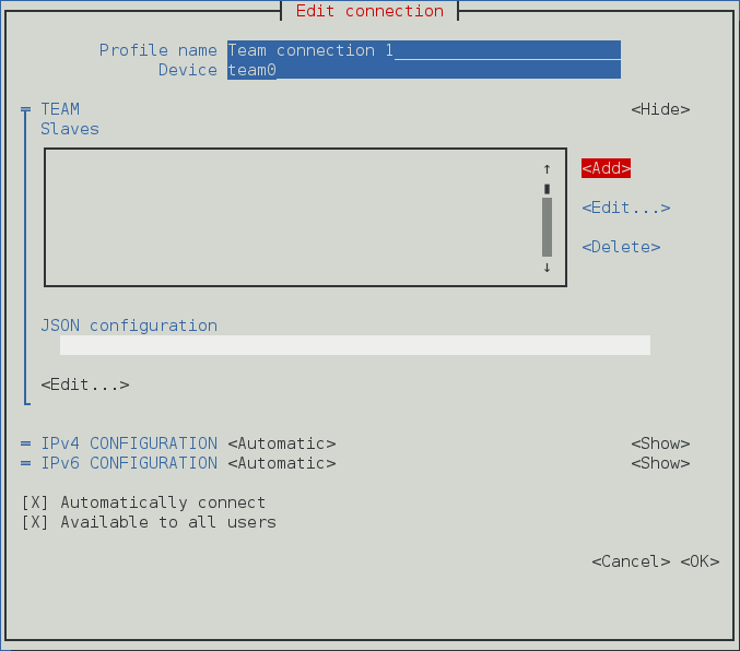
Figure 8.2. The NetworkManager Text User Interface Configuring a Team Connection menu
To add port interfaces to the team select
Add
, the
New Connection
screen opens. Once the type of Connection has been chosen select the
Create
button to cause the team's
Edit Connection
display to appear.
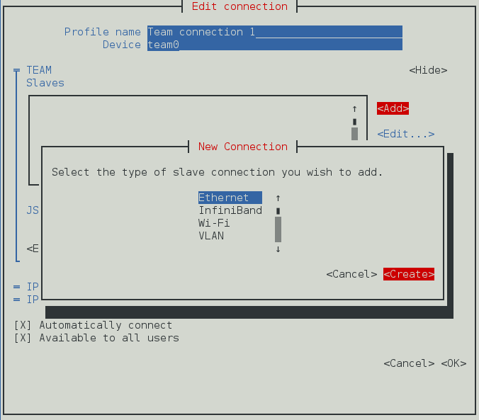
Figure 8.3. The NetworkManager Text User Interface Configuring a new Team Port Interface Connection menu
Enter the required port's device name or MAC address in the
Device
section. If required, enter a clone MAC address to be used as the team's MAC address by selecting
Show
to the right of the
Ethernet
label. Select the
OK
button.
If the device is specified without a MAC address the
Device
section will be automatically populated once the
Edit Connection
window is reloaded, but only if it successfully finds the device.
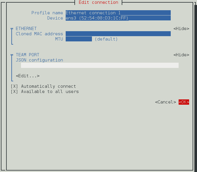
Figure 8.4. The NetworkManager Text User Interface Configuring a Team's Port Interface Connection menu
The name of the teamed port appears in the
Slaves
section. Repeat the above steps to add further port connections.
If custom port settings are to be applied select the
Edit
button under the
JSON configuration
section. This will launch a
vim
console where changes may be applied. Once finished write the changes from
vim
and then confirm that the displayed JSON string under
JSON configuration
matches what is intended.
Review and confirm the settings before selecting the
OK
button.
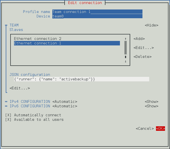
Figure 8.5. The NetworkManager Text User Interface Configuring a Team Connection menu
See
Section 8.13, “Configure teamd Runners”
for examples of JSON strings. Note that only the relevant sections from the example strings should be used for a team or port configuration using
nmtui
. Do not specify the
“
Device
”
as part of the JSON string. For example, only the JSON string after
“
device
”
but before
“
port
”
should be used in the Team JSON configuration field. All JSON strings relevant to a port must only be added in the port configuration field.
See
Section 3.2, “Configuring IP Networking with nmtui”
for information on installing
nmtui
.
8.10. Configure a Network Team Using the Command Line
8.10.1. Configure Network Teaming Using nmcli
To view the connections available on the system:
~]$ nmcli connection show
NAME UUID TYPE DEVICE
enp2s0 0e8185a1-f0fd-4802-99fb-bedbb31c689b 802-3-ethernet --
enp1s0 dfe1f57b-419d-4d1c-aaf5-245deab82487 802-3-ethernet --
To view the devices available on the system:
~]$nmcli device statusDEVICE TYPE STATE CONNECTION virbr0 bridge connected virbr0 ens3 ethernet connected ens3 To create a new team interface, with name ServerA:~]$NetworkManager will set its internal parameternmcli connection add type team ifname ServerAConnection 'team-ServerA' (b954c62f-5fdd-4339-97b0-40efac734c50) successfully added.connection.autoconnecttoyesand as noIPaddress was givenipv4.methodwill be set toauto. NetworkManager will also write a configuration file to/etc/sysconfig/network-scripts/ifcfg-team-ServerAwhere the corresponding ONBOOT will be set toyesand BOOTPROTO will be set todhcp. Note that manual changes to the ifcfg file will not be noticed by NetworkManager until the interface is next brought up. See Section 2.7, “Using NetworkManager with sysconfig files” for more information on using configuration files. To view the other values assigned:~]$As no JSON configuration file was specified the default values apply. See thenmcli con show team-ServerAconnection.id: team-ServerA connection.uuid: b954c62f-5fdd-4339-97b0-40efac734c50 connection.interface-name: ServerA connection.type: team connection.autoconnect: yes ipv4.method: auto [output truncated]teamd.conf(5)man page for more information on the team JSON parameters and their default values. Notice that the name was derived from the interface name by prepending the type. Alternatively, specify a name with thecon-nameoption as follows:~]$To view the team interfaces just configured, enter a command as follows:nmcli connection add type team con-name Team0 ifname ServerBConnection 'Team0' (5f7160a1-09f6-4204-8ff0-6d96a91218a7) successfully added.~]$To change the name assigned to a team, enter a command in the following format:nmcli con showNAME UUID TYPE DEVICE team-ServerA b954c62f-5fdd-4339-97b0-40efac734c50 team ServerA enp2s0 0e8185a1-f0fd-4802-99fb-bedbb31c689b 802-3-ethernet -- enp1s0 dfe1f57b-419d-4d1c-aaf5-245deab82487 802-3-ethernet -- Team0 5f7160a1-09f6-4204-8ff0-6d96a91218a7 team ServerBTo load a team configuration file for a team that already exists:nmcli con mod old-team-name connection.id new-team-nameYou can specify the team configuration either as a JSON string or provide a file name containing the configuration. The file name can include the path. In both cases, what is stored in thenmcli connection modify team-name team.config JSON-configteam.configproperty is the JSON string. In the case of a JSON string, use single quotes around the string and paste the entire string to the command line. To review theteam.configproperty:When thenmcli con show team-name | grep team.configteam.configproperty is set, all the other team properties are updated accordingly. It is also possible a more flexible way of exposing and setting particular team options without modifying directly the corresponding JSON string. You can do this by using the other available team properties to set the related team options one by one to the required values. As a result, theteam.configproperty is updated to match the new values. For example, to set theteam.link-watchersproperty which allows to specify one or multiplelink-watchers, enter a command in the following format:The requirednmcli connection modify team-nameteam.link-watchers"name=ethtool delay-up=5, name=nsna_ping target-host=target.host"link-watchersare separated by comma and the attributes which belong to the samelink-watcherare separated by space. To set theteam.runnerand theteam.link-watchersproperties, enter a command in the following format:This is equivalent to set thenmcli connection modify team-nameteam.runneractivebackupteam.link-watchers"name=ethtool delay-up=5, name=nsna_ping target-host=target.host"team.configproperty to the corresponding JSON string:To add an interface enp1s0 tonmcli connection modify team-nameteam.config'{"runner": {"name": "activebackup"}, "link_watch": [{"name": "ethtool", "delay_up": 5},{"name": "nsna_ping", "target_host ": "target.host"}]'Team0, with the name Team0-port1, issue a command as follows:~]$Similarly, to add another interface, enp2s0, with the name Team0-port2, issue a command as follows:nmcli con add type ethernet con-name Team0-port1 ifname enp1s0 slave-type team master Team0Connection 'Team0-port1' (ccd87704-c866-459e-8fe7-01b06cf1cffc) successfully added.~]$nmcli only supports Ethernet ports. To open a team, the ports must be brought up first as follows:nmcli con add type ethernet con-name Team0-port2 ifname enp2s0 slave-type team master Team0Connection 'Team0-port2' (a89ccff8-8202-411e-8ca6-2953b7db52dd) successfully added.~]$nmcli connection up Team0-port1Connection successfully activated (D-Bus active path: /org/freedesktop/NetworkManager/ActiveConnection/2)~]$You can verify that the team interface was brought up by the activation of the ports, as follows:nmcli connection up Team0-port2Connection successfully activated (D-Bus active path: /org/freedesktop/NetworkManager/ActiveConnection/3)~]$Alternatively, issue a command to open the team as follows:ip link3: Team0: <BROADCAST,MULTICAST,UP,LOWER_UP> mtu 1500 qdisc noqueue state UP mode DEFAULT link/ether 52:54:00:76:6f:f0 brd ff:ff:ff:ff:ff:f~]$See Section 3.3, “Configuring IP Networking with nmcli” for an introduction to nmclinmcli connection up Team0Connection successfully activated (D-Bus active path: /org/freedesktop/NetworkManager/ActiveConnection/4)
8.10.2. Creating a Network Team Using teamd
Note
Configurations created using teamd are not persistent, and as such it may be necessary to create a team using the steps defined in
Section 8.10.1, “Configure Network Teaming Using nmcli”
or
Section 8.10.3, “Creating a Network Team Using ifcfg Files”
.
To create a network team, a JSON format configuration file is required for the virtual interface that will serve as the interface to the team of ports or links. A quick way is to copy the example configuration files and then edit them using an editor running with
root
privileges. To list the available example configurations, enter the following command:
~]$ ls /usr/share/doc/teamd-*/example_configs/
activebackup_arp_ping_1.conf activebackup_multi_lw_1.conf loadbalance_2.conf
activebackup_arp_ping_2.conf activebackup_nsna_ping_1.conf loadbalance_3.conf
activebackup_ethtool_1.conf broadcast.conf random.conf
activebackup_ethtool_2.conf lacp_1.conf roundrobin_2.conf
activebackup_ethtool_3.conf loadbalance_1.conf roundrobin.conf
To view one of the included files, such as
activebackup_ethtool_1.conf
, enter the following command:
~]$cat /usr/share/doc/teamd-*/example_configs/activebackup_ethtool_1.conf"device": "team0", "runner": {"name": "activebackup"}, "link_watch": {"name": "ethtool"}, "ports": { "enp1s0": { "prio": -10, "sticky": true "enp2s0": { "prio": 100 Create a working configurations directory to storeteamdconfiguration files. For example, as normal user, enter a command with the following format:~]$Copy the file you have chosen to your working directory and edit it as necessary. As an example, you could use a command with the following format:mkdir ~/teamd_working_configs~]$To edit the file to suit your environment, for example to change the interfaces to be used as ports for the network team, open the file for editing as follows:cp /usr/share/doc/teamd-*/example_configs/activebackup_ethtool_1.conf \ ~/teamd_working_configs/activebackup_ethtool_1.conf~]$Make any necessary changes and save the file. See thevi ~/teamd_working_configs/activebackup_ethtool_1.confvi(1)man page for help on using the vi editor or use your preferred editor. Note that it is essential that the interfaces to be used as ports within the team must not be active, that is to say, they must be “down”, when adding them into a team device. To check their status, issue the following command:~]$In this example we see that both the interfaces we plan to use are “UP”. To take down an interface, issue a command asip link show1: lo: <LOOPBACK,UP,LOWER_UP> mtu 65536 qdisc noqueue state UNKNOWN mode DEFAULT link/loopback 00:00:00:00:00:00 brd 00:00:00:00:00:00 2: em1: <BROADCAST,MULTICAST,UP,LOWER_UP> mtu 1500 qdisc pfifo_fast state UP mode DEFAULT qlen 1000 link/ether 52:54:00:d5:f7:d4 brd ff:ff:ff:ff:ff:ff 3: em2: <BROADCAST,MULTICAST,UP,LOWER_UP> mtu 1500 qdisc pfifo_fast state UP mode DEFAULT qlen 1000 link/ether 52:54:00:d8:04:70 brd ff:ff:ff:ff:ff:ffrootin the following format:~]#Repeat for each interface as necessary. To create a team interface based on the configuration file, asip link set down em1rootuser, change to the working configurations directory (teamd_working_configs in this example):~]#Then issue a command in the following format:cd /home/userteamd_working_configs~]#Theteamd -g -f activebackup_ethtool_1.conf -dUsing team device "team0". Using PID file "/var/run/teamd/team0.pid" Using config file "/home/user/teamd_working_configs/activebackup_ethtool_1.conf"-goption is for debug messages,-foption is to specify the configuration file to load, and the-doption is to make the process run as a daemon after startup. See theteamd(8)man page for other options. To check the status of the team, issue the following command asroot:~]#To apply an address to the network team interface, team0, issue a command asteamdctl team0 statesetup: runner: activebackup ports: link watches: link summary: up instance[link_watch_0]: name: ethtool link: up link watches: link summary: up instance[link_watch_0]: name: ethtool link: up runner: active port: em1rootin the following format:~]#To check the IP address of a team interface, issue a command as follows:ip addr add 192.168.23.2/24 dev team0~]$To activate the team interface, or to bring it “up”, issue a command asip addr show team04: team0: <BROADCAST,MULTICAST,UP,LOWER_UP> mtu 1500 qdisc noqueue state UP link/ether 16:38:57:60:20:6f brd ff:ff:ff:ff:ff:ff inet 192.168.23.2/24 scope global team0 valid_lft forever preferred_lft forever inet6 2620:52:0:221d:1438:57ff:fe60:206f/64 scope global dynamic valid_lft 2591880sec preferred_lft 604680sec inet6 fe80::1438:57ff:fe60:206f/64 scope link valid_lft forever preferred_lft foreverrootin the following format:~]#To temporarily deactivate the team interface, or to take it “down”, issue a command asip link set dev team0 uprootin the following format:~]#To terminate, or kill, an instance of the team daemon, asip link set dev team0 downrootuser, issue a command in the following format:~]#Theteamd -t team0 -k-koption is to specify that the instance of the daemon associated with the device team0 is to be killed. See theteamd(8)man page for other options. For help on command-line options forteamd, issue the following command:~]$In addition, see theteamd -hteamd(8)man page.
8.10.3. Creating a Network Team Using ifcfg Files
To create a networking team using
ifcfg
files, create a file in the
/etc/sysconfig/network-scripts/
directory as follows:
DEVICE=team0
DEVICETYPE=Team
ONBOOT=yes
BOOTPROTO=none
IPADDR=192.168.11.1
PREFIX=24
TEAM_CONFIG='{"runner": {"name": "activebackup"}, "link_watch": {"name": "ethtool"}}'
This creates the interface to the team, in other words, this is the
master
.
To create a port to be a member of
team0
, create one or more files in the
/etc/sysconfig/network-scripts/
directory as follows:
DEVICE=enp1s0
HWADDR=D4:85:64:01:46:9E
DEVICETYPE=TeamPort
ONBOOT=yes
TEAM_MASTER=team0
TEAM_PORT_CONFIG='{"prio": 100}'
Add additional port interfaces similar to the above as required, changing the DEVICE and HWADDR field to match the ports (the network devices) being added. If port priority is not specified by
prio
it defaults to
0
; it accepts negative and positive values in the range
-32,767
to
+32,767
.
Specifying the hardware or MAC address using the
HWADDR
directive will influence the device naming procedure. This is explained in
Chapter 11,
Consistent Network Device Naming
.
To open the network team, issue the following command as
root
:
~]# ifup team0
To view the network team, issue the following command:
~]$ ip link show
8.10.4. Add a Port to a Network Team Using iputils
To add a port
em1
to a network team
team0
, using the
ip
utility, issue the following commands as
root
:
~]#Add additional ports as required. Team driver will bring ports up automatically.ip link set dev em1 down~]#ip link set dev em1 master team0
8.10.5. Listing the ports of a Team Using teamnl
To view or list the ports in a network team, using the
teamnl
utility, issue the following command as
root
:
~]# teamnl team0 ports
em2: up 100 fullduplex
em1: up 100 fullduplex
8.10.6. Configuring Options of a Team Using teamnl
To view or list all currently available options, using the
teamnl
utility, issue the following command as
root
:
~]# teamnl team0 options
To configure a team to use active backup mode, issue the following command as
root
:
~]# teamnl team0 setoption mode activebackup
8.10.7. Add an Address to a Network Team Using iputils
To add an address to a team
team0
, using the
ip
utility, issue the following command as
root
:
~]# ip addr add 192.168.252.2/24 dev team0
8.10.8. open an Interface to a Network Team Using iputils
To activate or
“
open
”
an interface to a network team,
team0
, using the
ip
utility, issue the following command as
root
:
~]# ip link set team0 up
8.10.9. Viewing the Active Port Options of a Team Using teamnl
To view or list the
activeport
option in a network team, using the
teamnl
utility, issue the following command as
root
:
~]# teamnl team0 getoption activeport
8.10.10. Setting the Active Port Options of a Team Using teamnl
To set the
activeport
option in a network team, using the
teamnl
utility, issue the following command as
root
:
~]# teamnl team0 setoption activeport 5
To check the change in team port options, issue the following command as
root
:
~]# teamnl team0 getoption activeport
8.11. Controlling teamd with teamdctl
In order to query a running instance of
teamd
for statistics or configuration information, or to make changes, the control tool
teamdctl
is used.
To view the current team state of a team
team0
, enter the following command as
root
:
~]# teamdctl team0 state view
For a more verbose output:
~]# teamdctl team0 state view -v
For a complete state dump in JSON format (useful for machine processing) of
team0
, use the following command:
~]# teamdctl team0 state dump
For a configuration dump in JSON format of
team0
, use the following command:
~]# teamdctl team0 config dump
To view the configuration of a port
em1
, that is part of a team
team0
, enter the following command:
~]# teamdctl team0 port config dump em1
8.11.1. Add a Port to a Network Team
To add a port
em1
to a network team
team0
, issue the following command as
root
:
~]# teamdctl team0 port add em1
Important
If using
teamdctl
directly to add a port, the port must be set to
down
. Otherwise the
teamdctl team0 port add em1
command will fail.
8.11.2. Remove a Port From a Network Team
To remove an interface
em1
from a network team
team0
, issue the following command as
root
:
~]# teamdctl team0 port remove em1
8.11.3. Applying a Sticky Setting to a Port in a Network Team
You can use the
teamdctl
command to apply a sticky setting to ensure that a specific port is used as an active link when it is available.
Prerequisites
-
You already created a team of network interfaces. As a result, you have a port ( em1 ) that you want to update the configuration of.
Procedure
To apply a JSON format configuration to a port
em1
in a network team
team0
, run the following commands:
Update the configuration of the sticky setting for
em1
:
~]# teamdctl team0 port config update em1 '{ "prio": 100, "sticky": true }'
Remove
em1
:
~]# teamdctl team0 port remove em1
Add
em1
again so that the sticky setting takes effect:
~]# teamdctl team0 port add em1
Note that the old configuration will be overwritten and that any options omitted will be reset to the default values. See the
teamdctl(8)
man page for more team daemon control tool command examples.
8.11.4. View the Configuration of a Port in a Network Team
To copy the configuration of a port
em1
in a network team
team0
, issue the following command as
root
:
~]# teamdctl team0 port config dump em1
This will dump the JSON format configuration of the port to standard output.
8.12. Verifying Network Configuration Teaming for Redundancy
Network redundancy is a process when devices are used for backup purposes to prevent or recover from a failure of a specific system. The following procedure describes how to verify the network configuration for teaming in redundancy:
Procedure
Ping the destination IP from the team interface. For example:
~]# ping -I team0 DSTADDR
View which interface is in
active
mode:
~]# teamdctl team0 state
setup:
runner: activebackup
ports:
enp1s0
link watches:
link summary: up
instance[link_watch_0]:
name: ethtool
link: up
down count: 0
enp2s0
link watches:
link summary: up
instance[link_watch_0]:
name: ethtool
link: up
down count: 0
runner:
active port: enp1s0
enp1s0
is the
active
interface.
Temporarily remove the network cable from the host.
There is no method to properly test link failure events using software utilities. Tools that deactivate connections, such as
ip
or
nmcli
, show only the driver’s ability to handle port configuration changes and not actual link failure events.
Check if the
backup
interface is up:
~]# teamdctl team0 state
setup:
runner: activebackup
ports:
enp1s0
link watches:
link summary: down
instance[link_watch_0]:
name: ethtool
link: down
down count: 1
enp2s0
link watches:
link summary: up
instance[link_watch_0]:
name: ethtool
link: up
down count: 0
runner:
active port: enp2s0
enp2s0
is now the
active
interface.
Check if you can still ping the destination IP from the team interface:
~]# ping -I team0 DSTADDR
8.13. Configure teamd Runners
Runners are units of code which are compiled into the Team daemon when an instance of the daemon is created. For an introduction to the
teamd
runners, see
Section 8.4, “Understanding the Network Teaming Daemon and the "Runners"”
.
8.13.1. Configure the broadcast Runner
To configure the broadcast runner, using an editor as
root
, add the following to the team JSON format configuration file:
"device": "team0",
"runner": {"name": "broadcast"},
"ports": {"em1": {}, "em2": {}}
Please see the
teamd.conf(5)
man page for more information.
8.13.2. Configure the random Runner
The random runner behaves similarly to the round-robin runner.
To configure the random runner, using an editor as
root
, add the following to the team JSON format configuration file:
"device": "team0",
"runner": {"name": "random"},
"ports": {"em1": {}, "em2": {}}
Please see the
teamd.conf(5)
man page for more information.
8.13.3. Configure the Round-robin Runner
To configure the round-robin runner, using an editor as
root
, add the following to the team JSON format configuration file:
"device": "team0",
"runner": {"name": "roundrobin"},
"ports": {"em1": {}, "em2": {}}
A very basic configuration for round-robin.
Please see the
teamd.conf(5)
man page for more information.
8.13.4. Configure the activebackup Runner
The active backup runner can use all of the link-watchers to determine the status of links in a team. Any one of the following examples can be added to the team JSON format configuration file:
"device": "team0",
"runner": {
"name": "activebackup"
"link_watch": {
"name": "ethtool"
"ports": {
"em1": {
"prio": -10,
"sticky": true
"em2": {
"prio": 100
This example configuration uses the active-backup runner with
ethtool
as the link watcher. Port
em2
has higher priority. The sticky flag ensures that if
em1
becomes active, it stays active as long as the link remains up.
"device": "team0",
"runner": {
"name": "activebackup"
"link_watch": {
"name": "ethtool"
"ports": {
"em1": {
"prio": -10,
"sticky": true,
"queue_id": 4
"em2": {
"prio": 100
This example configuration adds a queue ID of
4
. It uses active-backup runner with
ethtool
as the link watcher. Port
em2
has higher priority. But the sticky flag ensures that if
em1
becomes active, it will stay active as long as the link remains up.
To configure the activebackup runner using
ethtool
as the link watcher and applying a delay, using an editor as
root
, add the following to the team JSON format configuration file:
"device": "team0",
"runner": {
"name": "activebackup"
"link_watch": {
"name": "ethtool",
"delay_up": 2500,
"delay_down": 1000
"ports": {
"em1": {
"prio": -10,
"sticky": true
"em2": {
"prio": 100
This example configuration uses the active-backup runner with
ethtool
as the link watcher. Port
em2
has higher priority. But the sticky flag ensures that if
em1
becomes active, it stays active while the link remains up. Link changes are not propagated to the runner immediately, but delays are applied.
Please see the
teamd.conf(5)
man page for more information.
8.13.5. Configure the loadbalance Runner
This runner can be used for two types of load balancing, active and passive. In active mode, constant re-balancing of traffic is done by using statistics of recent traffic to share out traffic as evenly as possible. In passive mode, streams of traffic are distributed randomly across the available links. This has a speed advantage due to lower processing overhead. In high volume traffic applications this is often preferred as traffic usually consists of multiple stream which will be distributed randomly between the available links, in this way load sharing is accomplished without intervention by
teamd
.
To configure the loadbalance runner for passive transmit (Tx) load balancing, using an editor as
root
, add the following to the team JSON format configuration file:
"device": "team0",
"runner": {
"name": "loadbalance",
"tx_hash": ["eth", "ipv4", "ipv6"]
"ports": {"em1": {}, "em2": {}}
Configuration for hash-based passive transmit (Tx) load balancing.
To configure the loadbalance runner for active transmit (Tx) load balancing, using an editor as
root
, add the following to the team JSON format configuration file:
"device": "team0",
"runner": {
"name": "loadbalance",
"tx_hash": ["eth", "ipv4", "ipv6"],
"tx_balancer": {
"name": "basic"
"ports": {"em1": {}, "em2": {}}
Configuration for active transmit (Tx) load balancing using basic load balancer.
Please see the
teamd.conf(5)
man page for more information.
8.13.6. Configure the LACP (802.3ad) Runner
To configure the LACP runner using
ethtool
as a link watcher, using an editor as
root
, add the following to the team JSON format configuration file:
"device": "team0",
"runner": {
"name": "lacp",
"active": true,
"fast_rate": true,
"tx_hash": ["eth", "ipv4", "ipv6"]
"link_watch": {"name": "ethtool"},
"ports": {"em1": {}, "em2": {}}
Configuration for connection to a
link aggregation control protocol
(
LACP
) capable counterpart. The LACP runner should use
ethtool
to monitor the status of a link. Note that only
ethtool
can be used for link monitoring because, for example in the case of
arp_ping
, the link would never come up. The reason is that the link has to be established first and only after that can packets, ARP included, go through. Using
ethtool
prevents this because it monitors each link layer individually.
Active load balancing is possible with this runner in the same way as it is done for the loadbalance runner. To enable active transmit (Tx) load balancing, add the following section:
"tx_balancer": {
"name": "basic"
Please see the teamd.conf(5) man page for more information.
8.13.7. Configure Monitoring of the Link State
The following methods of link state monitoring are available. To implement one of the methods, add the JSON format string to the team JSON format configuration file using an editor running with
root
privileges.
8.13.7.1. Configure Ethtool for link-state Monitoring
To add or edit an existing delay, in milliseconds, between the link coming up and the runner being notified about it, add or edit a section as follows:
"link_watch": {
"name": "ethtool",
"delay_up": 2500
To add or edit an existing delay, in milliseconds, between the link going down and the runner being notified about it, add or edit a section as follows:
"link_watch": {
"name": "ethtool",
"delay_down": 1000
8.13.7.2. Configure ARP Ping for Link-state Monitoring
The team daemon
teamd
sends an ARP REQUEST to an address at the remote end of the link in order to determine if the link is up. The method used is the same as the
arping
utility but it does not use that utility.
Prepare a file containing the new configuration in JSON format similar to the following example:
"device": "team0",
"runner": {"name": "activebackup"},
"link_watch":{
"name": "arp_ping",
"interval": 100,
"missed_max": 30,
"source_host": "192.168.23.2",
"target_host": "192.168.23.1"
"ports": {
"em1": {
"prio": -10,
"sticky": true
"em2": {
"prio": 100
This configuration uses
arp_ping
as the link watcher. The
missed_max
option is a limit value of the maximum allowed number of missed replies (ARP replies for example). It should be chosen in conjunction with the
interval
option in order to determine the total time before a link is reported as down.
To load a new configuration for a team port
em2
, from a file containing a JSON configuration, issue the following command as
root
:
~]# teamdctl port config update em2 JSON-config-fileNote that the old configuration will be overwritten and that any options omitted will be reset to the default values. See the
teamdctl(8)
man page for more team daemon control tool command examples.
8.13.7.3. Configure IPv6 NA/NS for Link-state Monitoring
"device": "team0",
"runner": {"name": "activebackup"},
"link_watch": {
"name": "nsna_ping",
"interval": 200,
"missed_max": 15,
"target_host": "fe80::210:18ff:feaa:bbcc"
"ports": {
"em1": {
"prio": -10,
"sticky": true
"em2": {
"prio": 100
To configure the interval between sending NS/NA packets, add or edit a section as follows:
"link_watch": {
"name": "nsna_ping",
"interval": 200
Value is positive number in milliseconds. It should be chosen in conjunction with the
missed_max
option in order to determine the total time before a link is reported as down.
To configure the maximum number of missed NS/NA reply packets to allow before reporting the link as down, add or edit a section as follows:
"link_watch": {
"name": "nsna_ping",
"missed_max": 15
Maximum number of missed NS/NA reply packets. If this number is exceeded, the link is reported as down. The
missed_max
option is a limit value of the maximum allowed number of missed replies (ARP replies for example). It should be chosen in conjunction with the
interval
option in order to determine the total time before a link is reported as down.
To configure the host name that is resolved to the
IPv6
address target address for the NS/NA packets, add or edit a section as follows:
"link_watch": {
"name": "nsna_ping",
"target_host": "MyStorage"
The
“
target_host
”
option contains the host name to be converted to an
IPv6
address which will be used as the target address for the NS/NA packets. An
IPv6
address can be used in place of a host name.
Please see the
teamd.conf(5)
man page for more information.
8.13.8. Configure Port Selection Override
The physical port which transmits a frame is normally selected by the kernel part of the team driver, and is not relevant to the user or system administrator. The output port is selected using the policies of the selected team mode (
teamd
runner). On occasion however, it is helpful to direct certain classes of outgoing traffic to certain physical interfaces to implement slightly more complex policies. By default the team driver is multiqueue aware and 16 queues are created when the driver initializes. If more or less queues are required, the Netlink attribute
tx_queues
can be used to change this value during the team driver instance creation.
The queue ID for a port can be set by the port configuration option
queue_id
as follows:
"queue_id": 3
These queue ID's can be used in conjunction with the
tc
utility to configure a multiqueue queue discipline and filters to bias certain traffic to be transmitted on certain port devices. For example, if using the above configuration and wanting to force all traffic bound to
192.168.1.100
to use
enp1s0
in the team as its output device, issue commands as
root
in the following format:
~]#This mechanism of overriding runner selection logic in order to bind traffic to a specific port can be used with all runners.tc qdisc add dev team0 handle 1 root multiq~]#tc filter add dev team0 protocol ip parent 1: prio 1 u32 match ip dst \192.168.1.100 action skbedit queue_mapping 3
8.13.9. Configure BPF-based Tx Port Selectors
The loadbalance and LACP runners uses hashes of packets to sort network traffic flow. The hash computation mechanism is based on the
Berkeley Packet Filter
(
BPF
) code. The BPF code is used to generate a hash rather than make a policy decision for outgoing packets. The hash length is 8 bits giving 256 variants. This means many different
socket buffers
(
SKB
) can have the same hash and therefore pass traffic over the same link. The use of a short hash is a quick way to sort traffic into different streams for the purposes of load balancing across multiple links. In static mode, the hash is only used to decide out of which port the traffic should be sent. In active mode, the runner will continually reassign hashes to different ports in an attempt to reach a perfect balance.
The following fragment types or strings can be used for packet Tx hash computation:
eth
— Uses source and destination MAC addresses.
vlan
— Uses VLAN ID.
ipv4
— Uses source and destination
IPv4
addresses.
ipv6
— Uses source and destination
IPv6
addresses.
ip
— Uses source and destination
IPv4
and
IPv6
addresses.
l3
— Uses source and destination
IPv4
and
IPv6
addresses.
tcp
— Uses source and destination
TCP
ports.
udp
— Uses source and destination
UDP
ports.
sctp
— Uses source and destination
SCTP
ports.
l4
— Uses source and destination
TCP
and
UDP
and
SCTP
ports.
These strings can be used by adding a line in the following format to the load balance runner:
"tx_hash": ["eth", "ipv4", "ipv6"]See Section 8.13.5, “Configure the loadbalance Runner” for an example.
8.14. Creating a Network Team Using a GUI
8.14.1. Establishing a Team Connection
You can use
nm-connection-editor
to direct
NetworkManager
to create a team from two or more Wired or InfiniBand connections. It is not necessary to create the connections to be teamed first. They can be configured as part of the process to configure the team. You must have the MAC addresses of the interfaces available in order to complete the configuration process.
Procedure 8.1. Adding a New Team Connection Using nm-connection-editor
Follow the below steps to add a new team connection.
Enter
nm-connection-editor
in a terminal:
~]$ nm-connection-editor
Click the
Add
button. The
Choose a Connection Type
window appears. Select
Team
and click
Create
. The
Editing Team connection
1
window appears.
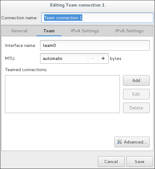
Figure 8.6. The NetworkManager Graphical User Interface Add a menu
On the
Team
tab, click
Add
and select the type of interface you want to use with the team connection. Click the
Create
button. Note that the dialog to select the port type only comes up when you create the first port; after that, it will automatically use that same type for all further ports.
The
Editing team0 slave 1
window appears.

Figure 8.7. The NetworkManager Graphical User Interface Add a
Slave
Connection
If custom port settings are to be applied, click on the
Team Port
tab and enter a JSON configuration string or import it from a file.
Click the
Save
button.
The name of the teamed port appears in the
Teamed connections
window. Click the
Add
button to add further port connections.
Review and confirm the settings and then click the
Save
button.
Edit the team-specific settings by referring to
Section 8.14.1.1, “Configuring the Team Tab”
below.
Procedure 8.2. Editing an Existing Team Connection
Follow the below steps to edit an existing team connection.
Enter
nm-connection-editor
in a terminal:
~]$ nm-connection-editor
Select the connection you want to edit and click the
Edit
button.
Select the
General
tab.
Five settings in the
Editing
dialog are common to the most connection types. See the
General
tab:
Connection name
— Enter a descriptive name for your network connection. This name is used to list this connection in the menu of the
Network
window.
Connection priority for auto-activation
— If the connection is set to autoconnect, the number is activated (
0
by default). The higher number means higher priority.
Automatically connect to this network when it is available
— Select this box if you want
NetworkManager
to auto-connect to this connection when it is available. See
the section called “Editing an Existing Connection with control-center”
for more information.
All users may connect to this network
— Select this box to create a connection available to all users on the system. Changing this setting may require root privileges. See
Section 3.4.5, “Managing System-wide and Private Connection Profiles with a GUI”
for details.
Automatically connect to VPN when using this connection
— Select this box if you want
NetworkManager
to auto-connect to a VPN connection when it is available. Select the VPN from the drop-down menu.
Firewall Zone
— Select the firewall zone from the drop-down menu. See the
Red Hat Enterprise Linux 7 Security Guide
for more information on firewall zones.
Edit the team-specific settings by referring to
Section 8.14.1.1, “Configuring the Team Tab”
below.
Saving Your New (or Modified) Connection and Making Further Configurations
Once you have finished editing your team connection, click the
Save
button to save your customized configuration.
Then, to configure:
IPv4
settings for the connection, click the
IPv4 Settings
tab and proceed to
Section 5.4, “Configuring IPv4 Settings”
IPv6
settings for the connection, click the
IPv6 Settings
tab and proceed to
Section 5.5, “Configuring IPv6 Settings”
.
8.14.1.1. Configuring the Team Tab
If you have already added a new team connection you can enter a custom JSON configuration string in the text box or import a configuration file. Click
Save
to apply the JSON configuration to the team interface.
For examples of JSON strings, see
Section 8.13, “Configure teamd Runners”
See
Procedure 8.1, “Adding a New Team Connection Using nm-connection-editor”
for instructions on how to add a new team.
8.15. Additional Resources
Installed Documentation
-
teamd(8)man page — Describes theteamdservice.teamdctl(8)man page — Describes theteamdcontrol tool.teamd.conf(5)man page — Describes theteamdconfiguration file.teamnl(8)man page — Describes theteamdNetlink library.bond2team(1)man page — Describes a tool to convert bonding options to team.
Online Documentation
- http://www.w3schools.com/js/js_json_syntax.asp
-
An explanation of JSON syntax.
Chapter 9. Configure Network Bridging
A network bridge is a link-layer device which forwards traffic between networks based on MAC addresses. It makes forwarding decisions based on a table of MAC addresses which it builds by listening to network traffic and thereby learning what hosts are connected to each network. A software bridge can be used within a Linux host in order to emulate a hardware bridge, for example in virtualization applications for sharing a NIC with one or more virtual NICs.
Note that a bridge cannot be established over Wi-Fi networks operating in
Ad-Hoc
or
Infrastructure
modes. This is due to the IEEE 802.11 standard that specifies the use of 3-address frames in Wi-Fi for the efficient use of airtime.
9.1. Configure Bridging Using the Text User Interface, nmtui
The text user interface tool
nmtui
can be used to configure bridging in a terminal window. Issue the following command to start the tool:
~]$ nmtui
The text user interface appears. Any invalid command prints a usage message.
To navigate, use the arrow keys or press
Tab
to step forwards and press
Shift
+
Tab
to step back through the options. Press
Enter
to select an option. The
Space
bar toggles the status of a check box.
From the starting menu, select
Edit a connection
. Select
Add
, the
New Connection
screen opens.
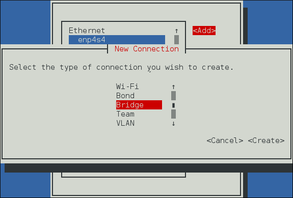
Figure 9.1. The NetworkManager Text User Interface Add a Bridge Connection menu
Select
Bridge
, the
Edit connection
screen opens.
To add port interfaces to the bridge select
Add
, the
New Connection
screen opens. Once the type of Connection has been chosen select the
Create
button to cause the bridge's
Edit Connection
display to appear.
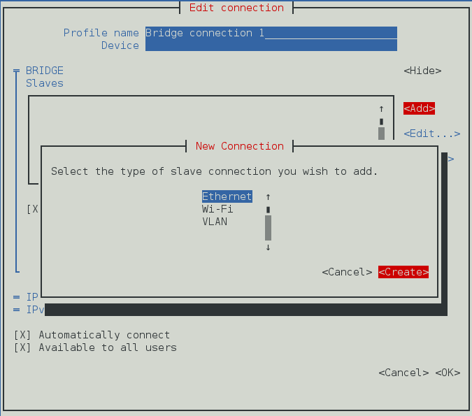
Figure 9.2. The NetworkManager Text User Interface Adding a new Bridge
Slave
Connection menu
Enter the required port's device name or MAC address in the
Device
section. If required, enter a clone MAC address to be used as the bridge's MAC address by selecting
Show
to the right of the
Ethernet
label. Select the
OK
button.
If the device is specified without a MAC address the
Device
section will be automatically populated once the
Edit Connection
window is reloaded, but only if it successfully finds the device.
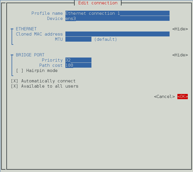
Figure 9.3. The NetworkManager Text User Interface Configuring a Bridge
Slave
Connection menu
The name of the bridge port appears in the
Slaves
section. Repeat the above steps to add further port connections.
Review and confirm the settings before selecting the
OK
button.
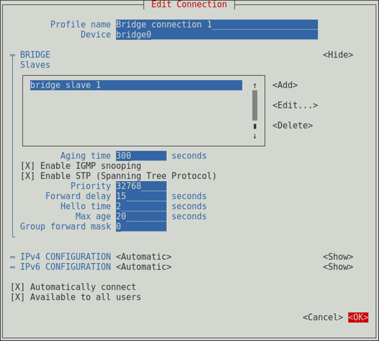
Figure 9.4. The NetworkManager Text User Interface Configuring a Bridge menu
See
Section 9.4.1.1, “Configuring the Bridge Tab”
for definitions of the bridge terms.
See
Section 3.2, “Configuring IP Networking with nmtui”
for information on installing
nmtui
.
9.2. Using the NetworkManager Command Line Tool, nmcli
To create a bridge, named
bridge-br0
, issue a command as follows as
root
:
~]# nmcli con add type bridge ifname br0
Connection 'bridge-br0' (6ad5bba6-98a0-4f20-839d-c997ba7668ad) successfully added.
If no interface name is specified, the name will default to
bridge
,
bridge-1
,
bridge-2
, and so on.
To view the connections, issue the following command:
~]$ nmcli con show
NAME UUID TYPE DEVICE
bridge-br0 79cf6a3e-0310-4a78-b759-bda1cc3eef8d bridge br0
enp1s0 4d5c449a-a6c5-451c-8206-3c9a4ec88bca 802-3-ethernet enp1s0
Spanning tree protocol
(
STP
) is enabled by default. The values used are from the IEEE 802.1D-1998 standard. To disable
STP
for this bridge, issue a command as follows as
root
:
~]# nmcli con modify bridge-br0 bridge.stp no
To re-enable
802.1D STP
for this bridge, issue a command as follows as
root
:
~]# nmcli con modify bridge-br0 bridge.stp yes
The default bridge priority for
802.1D STP
is
32768
. The lower number is preferred in root bridge selection. For example, a bridge with priority of
28672
would be selected as the root bridge in preference to a bridge with priority value of
32768
(the default). To create a bridge with a non-default value, issue a command as follows:
~]$ nmcli con add type bridge ifname br5 stp yes priority 28672
Connection 'bridge-br5' (86b83ad3-b466-4795-aeb6-4a66eb1856c7) successfully added.
The allowed values are in the range
0
to
65535
.
To change the bridge priority of an existing bridge to a non-default value, issue a command in the following format:
~]$ nmcli connection modify bridge-br5 bridge.priority 36864
The allowed values are in the range
0
to
65535
.
To configure a bridge connection to forward group addresses in the range from
01:80:C2:00:00:00
to
01:80:C2:00:00:0F
, change the
group-forward-mask
property. This property is a mask of 16 bits. Each bit corresponds to a group address in the above-mentioned range that must be forwarded. For example:
~]$ nmcli connection modify bridge-br5 bridge.group-forward-mask 8
Important
The
group-forward-mask
property cannot have any of the
0
,
1
,
2
bits set to
1
because those addresses are used for Spanning tree protocol (STP), Link Aggregation Control Protocol (LACP) and Ethernet MAC pause frames.
To view the bridge settings, issue the following command:
~]$ nmcli -f bridge con show bridge-br0
Further options for
802.1D STP
are listed in the bridge section of the
nmcli(1)
man page.
To add, or assign an interface, for example
enp1s0
, to the bridge
bridge-br0
, issue a command as follows:
~]$ nmcli con add type ethernet ifname enp1s0 master bridge-br0
Connection 'bridge-slave-enp1s0' (70ffae80-7428-4d9c-8cbd-2e35de72476e) successfully added.
To assign an existing connection to a bridge, proceed as follows:
Change its controller and port-type properties. For example to assign an existing VLAN connection named
vlan100
:
~]$ nmcli connection modify vlan100 master bridge-br0 slave-type bridge
Reactivate the connection to apply the changes:
~]$ nmcli connection up vlan100
To change a value using interactive mode, issue the following command:
~]$ nmcli connection edit bridge-br0
You will be placed at the
nmcli
prompt.
nmcli>See Section 3.3, “Configuring IP Networking with nmcli” for an introduction to nmcli .set bridge.priority 4096nmcli>saveConnection 'bridge-br0' (79cf6a3e-0310-4a78-b759-bda1cc3eef8d) successfully saved. nmcli>quit
9.3. Using the Command Line Interface (CLI)
9.3.1. Check if Bridging Kernel Module is Installed
In Red Hat Enterprise Linux 7, the bridging module is loaded by default. If necessary, you can make sure that the module is loaded by issuing the following command as
root
:
~]# modprobe --first-time bridge
modprobe: ERROR: could not insert 'bridge': Module already in kernel
To display information about the module, issue the following command:
~]$ modinfo bridge
See the
modprobe(8)
man page for more command options.
9.3.2. Create a Network Bridge
To create a network bridge, create a file in the
/etc/sysconfig/network-scripts/
directory called
ifcfg-br
N
, replacing
N
with the number for the interface, such as
0
.
The contents of the file is similar to whatever type of interface is getting bridged to, such as an Ethernet interface. The differences in this example are as follows:
The
DEVICE
directive is given an interface name as its argument in the format
br
N
, where
N
is replaced with the number of the interface.
The
TYPE
directive is given an argument
Bridge
. This directive determines the device type and the argument is case sensitive.
The bridge interface configuration file is given an
IP
address whereas the physical interface configuration file must only have a MAC address (see below).
An extra directive,
DELAY=0
, is added to prevent the bridge from waiting while it monitors traffic, learns where hosts are located, and builds a table of MAC addresses on which to base its filtering decisions. The default delay of 15 seconds is not needed if no routing loops are possible.
Example 9.1. Example ifcfg-br0 Interface Configuration File
The following is an example of a bridge interface configuration file using a static
IP
address:
DEVICE=br0 TYPE=Bridge IPADDR=192.168.1.1 PREFIX=24 BOOTPROTO=none ONBOOT=yes DELAY=0
To complete the bridge another interface is created, or an existing interface is modified, and pointed to the bridge interface.
Example 9.2. Example ifcfg-enp1s0 Interface Configuration File
The following is an example of an Ethernet interface configuration file pointing to a bridge interface. Configure your physical interface in
/etc/sysconfig/network-scripts/ifcfg-
device_name
, where
device_name
is the name of the interface
DEVICE=device_name TYPE=Ethernet HWADDR=AA:BB:CC:DD:EE:FF BOOTPROTO=none ONBOOT=yes BRIDGE=br0
Optionally specify a name using the NAME directive. If no name is specified, the
NetworkManager
plug-in,
ifcfg-rh
, will create a name for the connection profile in the form
“
Type Interface
”
. In this example, this means the bridge will be named
Bridge br0
. Alternately, if
NAME=bridge-br0
is added to the
ifcfg-br0
file the connection profile will be named
bridge-br0
.
For the
DEVICE
directive, almost any interface name could be used as it does not determine the device type.
TYPE=Ethernet
is not strictly required. If the
TYPE
directive is not set, the device is treated as an Ethernet device (unless its name explicitly matches a different interface configuration file).
The directives are case sensitive.
Specifying the hardware or MAC address using the
HWADDR
directive will influence the device naming procedure as explained in
Chapter 11,
Consistent Network Device Naming
.
Warning
If you are configuring bridging on a remote host, and you are connected to that host over the physical NIC you are configuring, consider the implications of losing connectivity before proceeding. You will lose connectivity when restarting the service and may not be able to regain connectivity if any errors have been made. Console, or out-of-band access is advised.
To open the new or recently configured interfaces, issue a command as
root
in the following format:
ifup device
nmcli con load
UUID
and then call
nmcli con up
UUID
.
Alternatively, to reload all interfaces, issue the following command as
root
:
~]# systemctl restart network
This command will stop the network service, start the network service, and then call
ifup
for all ifcfg files with
ONBOOT=yes
.
The default behavior is for
NetworkManager
not to be aware of changes to ifcfg files and to continue using the old configuration data until the interface is next brought up. This is set by the
monitor-connection-files
option in the
NetworkManager.conf
file. See the
NetworkManager.conf(5)
manual page for more information.
9.3.3. Network Bridge with Bond
An example of a network bridge formed from two or more bonded Ethernet interfaces will now be given as this is another common application in a virtualization environment. If you are not very familiar with the configuration files for bonded interfaces, see
Section 7.4.2, “Create a Channel Bonding Interface”
Create or edit two or more Ethernet interface configuration files, which are to be bonded, as follows:
DEVICE=interface_name TYPE=Ethernet SLAVE=yes MASTER=bond0 BOOTPROTO=none HWADDR=AA:BB:CC:DD:EE:FFUsing
interface_name
as the interface name is common practice but almost any name could be used.
Create or edit one interface configuration file,
/etc/sysconfig/network-scripts/ifcfg-bond0
, as follows:
DEVICE=bond0 ONBOOT=yes BONDING_OPTS='mode=1 miimon=100' BRIDGE=brbond0For further instructions and advice on configuring the bonding module and to view the list of bonding parameters, see Section 7.7, “Using Channel Bonding” . Create or edit one interface configuration file,
/etc/sysconfig/network-scripts/ifcfg-brbond0
, as follows:
DEVICE=brbond0 ONBOOT=yes TYPE=Bridge IPADDR=192.168.1.1 PREFIX=24We now have two or more interface configuration files with the
MASTER=bond0
directive. These point to the configuration file named
/etc/sysconfig/network-scripts/ifcfg-bond0
, which contains the
DEVICE=bond0
directive. This
ifcfg-bond0
in turn points to the
/etc/sysconfig/network-scripts/ifcfg-brbond0
configuration file, which contains the
IP
address, and acts as an interface to the virtual networks inside the host.
To open the new or recently configured interfaces, issue a command as
root
in the following format:
ifup device
nmcli con load
UUID
and then call
nmcli con up
UUID
.
Alternatively, to reload all interfaces, issue the following command as
root
:
~]# systemctl restart network
This command will stop the network service, start the network service, and then call
ifup
for all ifcfg files with
ONBOOT=yes
.
The default behavior is for
NetworkManager
not to be aware of changes to ifcfg files and to continue using the old configuration data until the interface is next brought up. This is set by the
monitor-connection-files
option in the
NetworkManager.conf
file. See the
NetworkManager.conf(5)
manual page for more information.
9.4. Configure Network Bridging Using a GUI
When starting a bridge interface,
NetworkManager
waits for at least one port to enter the
“
forwarding
”
state before beginning any network-dependent
IP
configuration such as
DHCP
or
IPv6
autoconfiguration. Static
IP
addressing is allowed to proceed before any ports or ports are connected or begin forwarding packets.
9.4.1. Establishing a Bridge Connection with a GUI
Procedure 9.1. Adding a New Bridge Connection Using nm-connection-editor
Follow the below instructions to create a new bridge connection:
Enter
nm-connection-editor
in a terminal:
~]$ nm-connection-editor
Click the
Add
button. The
Choose a Connection Type
window appears. Select
Bridge
and click
Create
. The
Editing Bridge connection
1
window appears.

Figure 9.5. Editing Bridge Connection 1
Add port devices by referring to
Procedure 9.3, “Adding a Port Interface to a Bridge”
below.
Procedure 9.2. Editing an Existing Bridge Connection
-
Enter nm-connection-editor in a terminal:
~]$ nm-connection-editorSelect the Bridge connection you want to edit. Click the Edit button.
Configuring the Connection Name, Auto-Connect Behavior, and Availability Settings
Five settings in the
Editing
dialog are common to all connection types, see the
General
tab:
Connection name
— Enter a descriptive name for your network connection. This name will be used to list this connection in the menu of the
Network
window.
Automatically connect to this network when it is available
— Select this box if you want
NetworkManager
to auto-connect to this connection when it is available. See
the section called “Editing an Existing Connection with control-center”
for more information.
All users may connect to this network
— Select this box to create a connection available to all users on the system. Changing this setting may require root privileges. See
Section 3.4.5, “Managing System-wide and Private Connection Profiles with a GUI”
for details.
Automatically connect to VPN when using this connection
— Select this box if you want
NetworkManager
to auto-connect to a VPN connection when it is available. Select the VPN from the dropdown menu.
Firewall Zone
— Select the Firewall Zone from the dropdown menu. See the
Red Hat Enterprise Linux 7 Security Guide
for more information on Firewall Zones.
9.4.1.1. Configuring the Bridge Tab
- Interface name
-
The name of the interface to the bridge.
- Bridged connections
-
One or more port interfaces.
- Aging time
-
The time, in seconds, a MAC address is kept in the MAC address forwarding database.
- Enable IGMP snooping
-
If required, select the check box to enable IGMP snooping on the device.
- Enable STP (Spanning Tree Protocol)
-
If required, select the check box to enable
STP. - Priority
-
The bridge priority; the bridge with the lowest priority will be elected as the root bridge.
- Forward delay
-
The time, in seconds, spent in both the Listening and Learning states before entering the Forwarding state. The default is 15 seconds.
- Hello time
-
The time interval, in seconds, between sending configuration information in bridge protocol data units (BPDU).
- Max age
-
The maximum time, in seconds, to store the configuration information from BPDUs. This value should be twice the Hello Time plus 1 but less than twice the Forwarding delay minus 1.
- Group forward mask
-
This property is a mask of group addresses that allows group addresses to be forwarded. In most cases, group addresses in the range from
01:80:C2:00:00:00to01:80:C2:00:00:0Fare not forwarded by the bridge device. This property is a mask of 16 bits, each corresponding to a group address in the above range, that must be forwarded. Note that theGroup forward maskproperty cannot have any of the0,1,2bits set to1because those addresses are used for Spanning tree protocol (STP), Link Aggregation Control Protocol (LACP) and Ethernet MAC pause frames.
Procedure 9.3. Adding a Port Interface to a Bridge
-
To add a port to a bridge, select the Bridge tab in the Editing Bridge connection 1 window. If necessary, open this window by following the procedure in Procedure 9.2, “Editing an Existing Bridge Connection” . Click Add . The Choose a Connection Type menu appears. Select the type of connection to be created from the list. Click Create . A window appropriate to the connection type selected appears.

Figure 9.6. The NetworkManager Graphical User Interface Add a Bridge Connection
-
Select the Bridge Port tab. Configure Priority and Path cost as required. Note the STP priority for a bridge port is limited by the Linux kernel. Although the standard allows a range of
0to255, Linux only allows0to63. The default is32in this case.
Figure 9.7. The NetworkManager Graphical User Interface Bridge Port tab
-
If required, select the Hairpin mode check box to enable forwarding of frames for external processing. Also known as virtual Ethernet port aggregator ( VEPA ) mode. Then, to configure: An Ethernet port, click the Ethernet tab and proceed to the section called “Basic Configuration Options ” , or; A Bond port, click the Bond tab and proceed to Section 7.8.1.1, “Configuring the Bond Tab” , or; A Team port, click the Team tab and proceed to Section 8.14.1.1, “Configuring the Team Tab” , or; An VLAN port, click the VLAN tab and proceed to Section 10.5.1.1, “Configuring the VLAN Tab” , or;
Saving Your New (or Modified) Connection and Making Further Configurations
Once you have finished editing your new bridge connection, click the
Save
button to save your customized configuration. If the profile was in use while being edited, power cycle the connection to make
NetworkManager
apply the changes. If the profile is OFF, set it to ON or select it in the network connection icon's menu. See
Section 3.4.1, “Connecting to a Network Using the
control-center
GUI”
for information on using your new or altered connection.
You can further configure an existing connection by selecting it in the
Network
window and clicking
Options
to return to the
Editing
dialog.
Then, to configure:
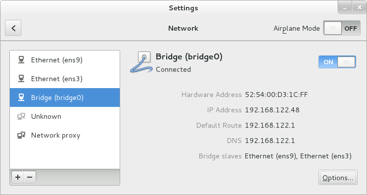
IPv4
settings for the connection, click the
IPv4 Settings
tab and proceed to
Section 5.4, “Configuring IPv4 Settings”
, or;
IPv6
settings for the connection, click the
IPv6 Settings
tab and proceed to
Section 5.5, “Configuring IPv6 Settings”
.
Once saved the Bridge will appear in the Network settings tool with each port showing in the display.
Figure 9.8. The NetworkManager Graphical User Interface with Bridge
9.5. Ethernet Bridge Configuration Using iproute
The iproute package can be used as an alternative to the bridge-utils. It allows to set bridge port options such as
priority
,
cost
or
state
.
To set port options for an interface
enp1s0
assigned to a bridge device, using the
ip
utility, issue the following command as
root
:
~]# ip link set enp1s0 type bridge_slave option
To select the available options, using the
ip
utility, issue the following command as
root
:
~]# ip link help bridge_slave
Usage: ... bridge_slave [ state STATE ] [ priority PRIO ] [cost COST ]
[ guard {on | off} ]
[ hairpin {on | off} ]
[ fastleave {on | off} ]
[ root_block {on | off} ]
[ learning {on | off} ]
[ flood {on | off} ]
For more details on the port options, see the
ip-link(8)
man page.
9.6. Additional Resources
-
nmcli(1)man page — Describes NetworkManager 's command‐line tool.nmcli-examples(5)man page — Gives examples of nmcli commands.nm-settings(5)man page — Description of settings and parameters of NetworkManager connections.ip-link(8)man page — Description of the bridge port options.
Chapter 10. Configure 802.1Q VLAN tagging
To create a VLAN, an interface is created on top of another interface referred to as the
parent interface
. The VLAN interface will tag packets with the VLAN ID as they pass through the interface, and returning packets will be untagged. VLAN interface can be configured similarly to any other interface. The parent interface does not need to be an Ethernet interface. An 802.1Q VLAN tagging interface can be created on top of bridge, bond, and team interfaces, however there are some things to note:
In the case of VLANs over bonds, it is important that the bond has ports and that they are
“
up
”
before opening the VLAN interface. Adding a VLAN interface to a bond without ports does not work.
A VLAN port cannot be configured on a bond with the
fail_over_mac=follow
option, because the VLAN virtual device cannot change its MAC address to match the parent's new MAC address. In such a case, traffic would still be sent with the now incorrect source MAC address.
Sending VLAN tagged packets through a network switch requires the switch to be properly configured. For example, ports on Cisco switches must be assigned to one VLAN or be configured as trunk ports to accept tagged packets from multiple VLANs. Some vendor switches allow untagged frames of the
native VLAN
to be processed by a trunk port. Some devices allow you to enable or disable the
native VLAN
, other devices have it disabled by default. Consequence of this disparity may result in
native VLAN
misconfiguration between two different switches, posing a security risk. For example:
One switch uses
native VLAN 1
while the other uses
native VLAN 10
. If the frames are allowed to pass without the tag being inserted, an attacker is able to jump VLANs - this common network penetration technique is also known as
VLAN hopping
.
To minimize security risks, configure your interface as follows:
- Switches
-
Unless you need them, disable trunk ports. If you need trunk ports, disable native VLAN , so that untagged frames are not allowed.
- Red Hat Enterprise Linux server
-
Use the nftables or ebtables utilities to drop untagged frames in ingress filtering. Some older network interface cards, loopback interfaces, Wimax cards, and some InfiniBand devices, are said to be VLAN challenged , meaning they cannot support VLANs. This is usually because the devices cannot cope with VLAN headers and the larger MTU size associated with tagged packets. Bonding on top of VLAN is not supported by Red Hat. See the Red Hat Knowledgebase article Whether configuring bond on top of VLAN as port interfaces is a valid configuration? for more information.
10.1. Selecting VLAN Interface Configuration Methods
-
To configure a VLAN interface using NetworkManager 's text user interface tool, nmtui , proceed to Section 10.2, “Configure 802.1Q VLAN tagging Using the Text User Interface, nmtui” To configure a VLAN interface using NetworkManager 's command-line tool, nmcli , proceed to Section 10.3, “Configure 802.1Q VLAN Tagging Using the Command Line Tool, nmcli” To configure a network interface manually , see Section 10.4, “Configure 802.1Q VLAN Tagging Using the Command Line” . To configure a network using graphical user interface tools , proceed to Section 10.5, “Configure 802.1Q VLAN Tagging Using a GUI”
10.2. Configure 802.1Q VLAN tagging Using the Text User Interface, nmtui
The text user interface tool
nmtui
can be used to configure 802.1Q VLANs in a terminal window. Issue the following command to start the tool:
~]$ nmtui
The text user interface appears. Any invalid command prints a usage message.
To navigate, use the arrow keys or press
Tab
to step forwards and press
Shift
+
Tab
to step back through the options. Press
Enter
to select an option. The
Space
bar toggles the status of a check box.
From the starting menu, select
Edit a connection
. Select
Add
, the
New Connection
screen opens.
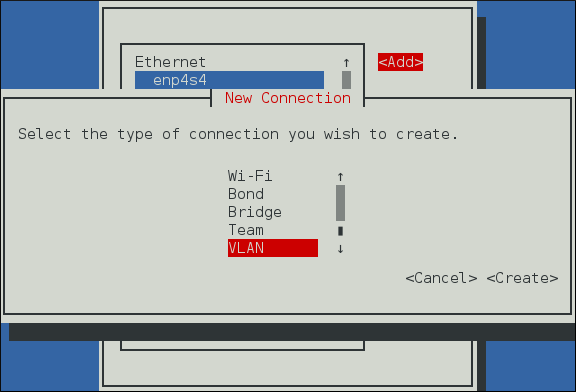
Figure 10.1. The NetworkManager Text User Interface Add a VLAN Connection menu
Select
VLAN
, the
Edit connection
screen opens. Follow the on-screen prompts to complete the configuration.

Figure 10.2. The NetworkManager Text User Interface Configuring a VLAN Connection menu
See
Section 10.5.1.1, “Configuring the VLAN Tab”
for definitions of the VLAN terms.
See
Section 3.2, “Configuring IP Networking with nmtui”
for information on installing
nmtui
.
10.3. Configure 802.1Q VLAN Tagging Using the Command Line Tool, nmcli
To view the available interfaces on the system, issue a command as follows:
~]$ nmcli con show
NAME UUID TYPE DEVICE
System enp2s0 9c92fad9-6ecb-3e6c-eb4d-8a47c6f50c04 802-3-ethernet enp2s0
System enp1s0 5fb06bd0-0bb0-7ffb-45f1-d6edd65f3e03 802-3-ethernet enp1s0
Note that the NAME field in the output always denotes the connection ID. It is not the interface name even though it might look the same. The ID can be used in
nmcli connection
commands to identify a connection. Use the DEVICE name with other applications such as
firewalld
.
To create an 802.1Q VLAN interface on Ethernet interface
enp1s0
, with VLAN interface
VLAN10
and ID
10
, issue a command as follows:
~]$ nmcli con add type vlan ifname VLAN10 dev enp1s0 id 10
Connection 'vlan-VLAN10' (37750b4a-8ef5-40e6-be9b-4fb21a4b6d17) successfully added.
Note that as no
con-name
was given for the VLAN interface, the name was derived from the interface name by prepending the type. Alternatively, specify a name with the
con-name
option as follows:
~]$ nmcli con add type vlan con-name VLAN12 dev enp1s0 id 12
Connection 'VLAN12' (b796c16a-9f5f-441c-835c-f594d40e6533) successfully added.
Assigning Addresses to VLAN Interfaces
You can use the same
nmcli
commands to assign static and dynamic interface addresses as with any other interface.
For example, a command to create a VLAN interface with a static
IPv4
address and gateway is as follows:
~]$To create a VLAN interface with dynamically assigned addressing, issue a command as follows:nmcli con add type vlan con-name VLAN20 dev enp1s0 id 20 ip4 10.10.10.10/24 \gw4 10.10.10.254
~]$ nmcli con add type vlan con-name VLAN30 dev enp1s0 id 30
See
Section 3.3.6, “Connecting to a Network Using nmcli”
for examples of using
nmcli
commands to configure interfaces.
To review the VLAN interfaces created, issue a command as follows:
~]$ nmcli con show
NAME UUID TYPE DEVICE
VLAN12 4129a37d-4feb-4be5-ac17-14a193821755 vlan enp1s0.12
System enp2s0 9c92fad9-6ecb-3e6c-eb4d-8a47c6f50c04 802-3-ethernet enp2s0
System enp1s0 5fb06bd0-0bb0-7ffb-45f1-d6edd65f3e03 802-3-ethernet enp1s0
vlan-VLAN10 1be91581-11c2-461a-b40d-893d42fed4f4 vlan VLAN10
To view detailed information about the newly configured connection, issue a command as follows:
~]$ nmcli -p con show VLAN12
===============================================================================
Connection profile details (VLAN12)
===============================================================================
connection.id: VLAN12
connection.uuid: 4129a37d-4feb-4be5-ac17-14a193821755
connection.interface-name: --
connection.type: vlan
connection.autoconnect: yes
-------------------------------------------------------------------------------
802-3-ethernet.port: --
802-3-ethernet.speed: 0
802-3-ethernet.duplex: --
802-3-ethernet.auto-negotiate: yes
802-3-ethernet.mac-address: --
802-3-ethernet.cloned-mac-address: --
802-3-ethernet.mac-address-blacklist:
802-3-ethernet.mtu: auto
vlan.interface-name: --
vlan.parent: enp1s0
vlan.id: 12
vlan.flags: 0 (NONE)
vlan.ingress-priority-map:
vlan.egress-priority-map:
-------------------------------------------------------------------------------
===============================================================================
Activate connection details (4129a37d-4feb-4be5-ac17-14a193821755)
===============================================================================
GENERAL.NAME: VLAN12
GENERAL.UUID: 4129a37d-4feb-4be5-ac17-14a193821755
GENERAL.DEVICES: enp1s0.12
GENERAL.STATE: activating
[output truncated]
Further options for the VLAN command are listed in the VLAN section of the
nmcli(1)
man page. In the man pages the device on which the VLAN is created is referred to as the parent device. In the example above the device was specified by its interface name,
enp1s0
, it can also be specified by the connection UUID or MAC address.
To create an 802.1Q VLAN connection profile with ingress priority mapping on Ethernet interface
enp2s0
, with name
VLAN1
and ID
13
, issue a command as follows:
~]$ nmcli con add type vlan con-name VLAN1 dev enp2s0 id 13 ingress "2:3,3:5"
To view all the parameters associated with the VLAN created above, issue a command as follows:
~]$ nmcli connection show vlan-VLAN10
To change the MTU, issue a command as follows:
~]$ nmcli connection modify vlan-VLAN10 802.mtu 1496
The MTU setting determines the maximum size of the network layer packet. The maximum size of the payload the link-layer frame can carry in turn limits the network layer MTU. For standard Ethernet frames this means an MTU of 1500 bytes. It should not be necessary to change the MTU when setting up a VLAN as the link-layer header is increased in size by 4 bytes to accommodate the 802.1Q tag.
At time of writing,
connection.interface-name
and
vlan.interface-name
have to be the same (if they are set). They must therefore be changed simultaneously using
nmcli
's interactive mode. To change a VLAN connections name, issue commands as follows:
~]$The nmcli utility can be used to set and clearnmcli con edit vlan-VLAN10nmcli>set vlan.interface-name superVLANnmcli>set connection.interface-name superVLANnmcli>savenmcli>quit
ioctl
flags which change the way the 802.1Q code functions. The following VLAN flags are supported by
NetworkManager
:
0x01 - reordering of output packet headers
0x02 - use GVRP protocol
0x04 - loose binding of the interface and its master
The state of the VLAN is synchronized to the state of the parent or master interface (the interface or device on which the VLAN is created). If the parent interface is set to the
“
down
”
administrative state then all associated VLANs are set down and all routes are flushed from the routing table. Flag
0x04
enables a
loose binding
mode, in which only the operational state is passed from the parent to the associated VLANs, but the VLAN device state is not changed.
To set a VLAN flag, issue a command as follows:
~]$ nmcli connection modify vlan-VLAN10 vlan.flags 1
See
Section 3.3, “Configuring IP Networking with nmcli”
for an introduction to
nmcli
.
10.4. Configure 802.1Q VLAN Tagging Using the Command Line
In Red Hat Enterprise Linux 7, the
8021q
module is loaded by default. If necessary, you can make sure that the module is loaded by issuing the following command as
root
:
~]# modprobe --first-time 8021q
modprobe: ERROR: could not insert '8021q': Module already in kernel
To display information about the module, issue the following command:
~]$ modinfo 8021q
See the
modprobe(8)
man page for more command options.
10.4.1. Setting Up 802.1Q VLAN Tagging Using ifcfg Files
-
Configure the parent interface in
/etc/sysconfig/network-scripts/ifcfg- device_name, where device_name is the name of the interface:DEVICE=interface_name TYPE=Ethernet BOOTPROTO=none ONBOOT=yes
-
Configure the VLAN interface configuration in the
/etc/sysconfig/network-scripts/directory. The configuration file name should be the parent interface plus a.character plus the VLAN ID number. For example, if the VLAN ID is 192, and the parent interface is enp1s0 , then the configuration file name should beifcfg-enp1s0.192:DEVICE=enp1s0.192 BOOTPROTO=none ONBOOT=yes IPADDR=192.168.1.1 PREFIX=24 NETWORK=192.168.1.0 VLAN=yes
If there is a need to configure a second VLAN, with for example, VLAN ID 193, on the same interface, enp1s0 , add a new file with the nameenp1s0.193with the VLAN configuration details. Restart the networking service in order for the changes to take effect. Asrootissue the following command:~]#
systemctl restart network
10.4.2. Configure 802.1Q VLAN Tagging Using ip Commands
To create an 802.1Q VLAN interface on Ethernet interface
enp1s0
, with name
VLAN8
and ID
8
, issue a command as
root
as follows:
~]# ip link add link enp1s0 name enp1s0.8 type vlan id 8
To view the VLAN, issue the following command:
~]$ ip -d link show enp1s0.8
4: enp1s0.8@enp1s0: <BROADCAST,MULTICAST,UP,LOWER_UP> mtu 1500 qdisc noqueue state UP mode DEFAULT
link/ether 52:54:00:ce:5f:6c brd ff:ff:ff:ff:ff:ff promiscuity 0
vlan protocol 802.1Q id 8 <REORDER_HDR>
Note that the
ip
utility interprets the VLAN ID as a hexadecimal value if it is preceded by
0x
and as an octal value if it has a leading
0
. This means that in order to assign a VLAN ID with a decimal value of
22
, you must not add any leading zeros.
To remove the VLAN, issue a command as
root
as follows:
~]# ip link delete enp1s0.8
To use multiple interfaces belonging to multiple VLANs, create locally
enp1s0.1
and
enp1s0.2
with the appropriate VLAN ID on top of a physical interface
enp1s0
:
~]#Note that running a network sniffer on a physical device, you can capture the tagged frames reaching the physical device, even if no VLAN device is configured on top of enp1s0 . For example:ip link add link enp1s0 name enp1s0.1 type vlan id 1ip link set dev enp1s0.1 up~]#ip link add link enp1s0 name enp1s0.2 type vlan id 2ip link set dev enp1s0.2 up
tcpdump -nnei enp1s0 -vvvVLAN interfaces created using ip commands at the command prompt will be lost if the system is shutdown or restarted. To configure VLAN interfaces to be persistent after a system restart, use
ifcfg
files. See
Section 10.4.1, “Setting Up 802.1Q VLAN Tagging Using ifcfg Files”
10.5. Configure 802.1Q VLAN Tagging Using a GUI
10.5.1. Establishing a VLAN Connection
You can use
nm-connection-editor
to create a VLAN using an existing interface as the parent interface. Note that VLAN devices are only created automatically if the parent interface is set to connect automatically.
Procedure 10.1. Adding a New VLAN Connection Using nm-connection-editor
-
Enter nm-connection-editor in a terminal:
~]$ nm-connection-editorClick the Add button. The Choose a Connection Type window appears. Select VLAN and click Create . The Editing VLAN connection 1 window appears. On the VLAN tab, select the parent interface from the drop-down list you want to use for the VLAN connection. Enter the VLAN ID Enter a VLAN interface name. This is the name of the VLAN interface that will be created. For example,enp1s0.1orvlan2. (Normally this is either the parent interface name plus “.” and the VLAN ID, or “vlan” plus the VLAN ID.) Review and confirm the settings and then click the Save button. To edit the VLAN-specific settings see Section 10.5.1.1, “Configuring the VLAN Tab” .
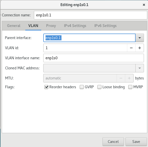
Figure 10.3. Adding a New VLAN Connection Using nm-connection-editor
Procedure 10.2. Editing an Existing VLAN Connection
Follow these steps to edit an existing VLAN connection.
Enter
nm-connection-editor
in a terminal:
~]$ nm-connection-editor
Select the connection you want to edit and click the
Edit
button.
Select the
General
tab.
Configure the connection name, auto-connect behavior, and availability settings.
These settings in the
Editing
dialog are common to all connection types:
Connection name
— Enter a descriptive name for your network connection. This name will be used to list this connection in the
VLAN
section of the
Network
window.
Automatically connect to this network when it is available
— Select this box if you want
NetworkManager
to auto-connect to this connection when it is available. Refer to
the section called “Editing an Existing Connection with control-center”
for more information.
Available to all users
— Select this box to create a connection available to all users on the system. Changing this setting may require root privileges. Refer to
Section 3.4.5, “Managing System-wide and Private Connection Profiles with a GUI”
for details.
To edit the VLAN-specific settings see
Section 10.5.1.1, “Configuring the VLAN Tab”
.
Saving Your New (or Modified) Connection and Making Further Configurations
Once you have finished editing your VLAN connection, click the
Save
button to save your customized configuration.
Then, to configure:
IPv4
settings for the connection, click the
IPv4 Settings
tab and proceed to
Section 5.4, “Configuring IPv4 Settings”
.
IPv6
settings for the connection, click the
IPv6 Settings
tab and proceed to
Section 5.5, “Configuring IPv6 Settings”
.
10.5.1.1. Configuring the VLAN Tab
If you have already added a new VLAN connection (see
Procedure 10.1, “Adding a New VLAN Connection Using nm-connection-editor”
for instructions), you can edit the
VLAN
tab to set the parent interface and the VLAN ID.
- Parent Interface
-
A previously configured interface can be selected in the drop-down list.
- VLAN ID
-
The identification number to be used to tag the VLAN network traffic.
- VLAN interface name
-
The name of the VLAN interface that will be created. For example,
enp1s0.1orvlan2. - Cloned MAC address
-
Optionally sets an alternate MAC address to use for identifying the VLAN interface. This can be used to change the source MAC address for packets sent on this VLAN. Optionally sets a Maximum Transmission Unit (MTU) size to be used for packets to be sent over the VLAN connection.
10.6. VLAN on Bond and Bridge Using ip Commands
To use VLANs over bonds and bridges, proceed as follows:
Add a bond device as
root
:
# ip link add bond0 type bond
# ip link set bond0 type bond miimon 100 mode active-backup
# ip link set em1 down
# ip link set em1 master bond0
# ip link set em2 down
# ip link set em2 master bond0
# ip link set bond0 up
Set VLAN on the bond device:
# ip link add link bond0 name bond0.2 type vlan id 2
# ip link set bond0.2 up
Add the bridge device and attach VLAN to it:
# ip link add br0 type bridge
# ip link set bond0.2 master br0
# ip link set br0 up
10.7. VLAN on Bond and Bridge Using the NetworkManager Command Line Tool, nmcli
To use VLANs over bonds and bridges, proceed as follows:
Add a bond device:
~]$ nmcli connection add type bond con-name Bond0 ifname bond0 bond.options "mode=active-backup,miimon=100" ipv4.method disabled ipv6.method ignore
Note that in this case a bond connection serves only as a "lower interface" for VLAN, and does not get any IP address. Therefore, the
ipv4.method disabled
and
ipv6.method ignore
parameters have been added on the command line.
Add ports to the bond device:
~]$Add a bridge device:nmcli connection add type ethernet con-name Slave1 ifname em1 master bond0 slave-type bond~]$nmcli connection add type ethernet con-name Slave2 ifname em2 master bond0 slave-type bond
~]$ nmcli connection add type bridge con-name Bridge0 ifname br0 ip4 192.0.2.1/24
Add a VLAN interface on top of bond, assigned to the bridge device:
~]$ nmcli connection add type vlan con-name Vlan2 ifname bond0.2 dev bond0 id 2 master br0 slave-type bridge
View the created connections:
~]$ nmcli connection show
NAME UUID TYPE DEVICE
Bond0 f05806fa-72c3-4803-8743-2377f0c10bed bond bond0
Bridge0 22d3c0de-d79a-4779-80eb-10718c2bed61 bridge br0
Slave1 e59e13cb-d749-4df2-aee6-de3bfaec698c 802-3-ethernet em1
Slave2 25361a76-6b3c-4ae5-9073-005be5ab8b1c 802-3-ethernet em2
Vlan2 e2333426-eea4-4f5d-a589-336f032ec822 vlan bond0.2
10.8. Configuring VLAN switchport mode
Red Hat Enterprise Linux machines are often used as routers and enable an advanced VLAN configuration on their network interfaces. You need to set
switchport mode
when the Ethernet interface is connected to a switch and there are VLANs running over the physical interface. A Red Hat Enterprise Linux server or workstation is usually connected to only one VLAN, which makes
switchport mode access
suitable, and the default setting.
In certain scenarios, multiple tagged VLANs use the same physical link, that is Ethernet between the switch and Red Hat Enterprise Linux machine, which requires
switchport mode trunk
to be configured on both ends.
For example, when a Red Hat Enterprise Linux machine is used as a router, the machine needs to forward tagged packets from the various VLANs behind the router to the switch over the same physical Ethernet, and maintain separation between those VLANs.
With the setup described, for example, in
Section 10.3, “Configure 802.1Q VLAN Tagging Using the Command Line Tool, nmcli”
, use the Cisco
switchport mode trunk
. If you only set an IP address on an interface, use Cisco
switchport mode access
.
10.9. Additional Resources
-
ip-link(8)man page — Describes the ip utility's network device configuration commands.nmcli(1)man page — Describes NetworkManager 's command‐line tool.nmcli-examples(5)man page — Gives examples of nmcli commands.nm-settings(5)man page — Description of settings and parameters of NetworkManager connections.nm-settings-ifcfg-rh(5)man page — Description of ifcfg-rh settings in the/etc/sysconfig/network-scripts/ifcfg-*files.
Chapter 11. Consistent Network Device Naming
Red Hat Enterprise Linux provides methods for consistent and predictable network device naming for network interfaces. These features change the name of network interfaces on a system in order to make locating and differentiating the interfaces easier.
Traditionally, network interfaces in Linux are enumerated as
eth[0123…]s0
, but these names do not necessarily correspond to actual labels on the chassis. Modern server platforms with multiple network adapters can encounter non-deterministic and counter-intuitive naming of these interfaces. This affects both network adapters embedded on the motherboard (
Lan-on-Motherboard
, or
LOM
) and add-in (single and multiport) adapters.
In Red Hat Enterprise Linux,
udev
supports a number of different naming schemes. The default is to assign fixed names based on firmware, topology, and location information. This has the advantage that the names are fully automatic, fully predictable, that they stay fixed even if hardware is added or removed (no re-enumeration takes place), and that broken hardware can be replaced seamlessly. The disadvantage is that they are sometimes harder to read than the
eth
or
wla
names traditionally used. For example:
enp5s0
.
Warning
Red Hat does not support systems with consistent device naming disabled. For further details, see
Is it safe to set net.ifnames=0?
11.1. Naming Schemes Hierarchy
By default,
systemd
will name interfaces using the following policy to apply the supported naming schemes:
Scheme 1:
Names incorporating Firmware or BIOS provided index numbers for on-board devices (example:
eno1
), are applied if that information from the firmware or BIOS is applicable and available, else falling back to scheme 2.
Scheme 2:
Names incorporating Firmware or BIOS provided PCI Express hotplug slot index numbers (example:
ens1
) are applied if that information from the firmware or BIOS is applicable and available, else falling back to scheme 3.
Scheme 3:
Names incorporating physical location of the connector of the hardware (example:
enp2s0
), are applied if applicable, else falling directly back to scheme 5 in all other cases.
Scheme 4:
Names incorporating interface's MAC address (example:
enx78e7d1ea46da
), is not used by default, but is available if the user chooses.
Scheme 5:
The traditional unpredictable kernel naming scheme, is used if all other methods fail (example:
eth0
).
This policy, the procedure outlined above, is the default. If the system has
biosdevname
enabled, it will be used. Note that enabling
biosdevname
requires passing
biosdevname=1
as a kernel command-line parameter, except in the case of a Dell system, where
biosdevname
will be used by default as long as it is installed. If the user has added
udev
rules which change the name of the kernel devices, those rules will take precedence.
11.2. Understanding the Device Renaming Procedure
The device name procedure in detail is as follows:
A rule in
/usr/lib/udev/rules.d/60-net.rules
instructs the
udev
helper utility,
/lib/udev/rename_device
, to look into all
/etc/sysconfig/network-scripts/ifcfg-
suffix
files. If it finds an
ifcfg
file with a
HWADDR
entry matching the MAC address of an interface it renames the interface to the name given in the
ifcfg
file by the
DEVICE
directive.
A rule in
/usr/lib/udev/rules.d/71-biosdevname.rules
instructs
biosdevname
to rename the interface according to its naming policy, provided that it was not renamed in a previous step,
biosdevname
is installed, and
biosdevname=0
was not given as a kernel command on the boot command line.
A rule in
/lib/udev/rules.d/75-net-description.rules
instructs
udev
to fill in the internal
udev
device property values ID_NET_NAME_ONBOARD, ID_NET_NAME_SLOT, ID_NET_NAME_PATH, ID_NET_NAME_MAC by examining the network interface device. Note, that some device properties might be undefined.
A rule in
/usr/lib/udev/rules.d/80-net-name-slot.rules
instructs
udev
to rename the interface, provided that it was not renamed in step 1 or 2, and the kernel parameter
net.ifnames=0
was not given, according to the following priority: ID_NET_NAME_ONBOARD, ID_NET_NAME_SLOT, ID_NET_NAME_PATH. It falls through to the next in the list, if one is unset. If none of these are set, then the interface will not be renamed.
Steps 3 and 4 are implementing the naming schemes 1, 2, 3, and optionally 4, described in
Section 11.1, “Naming Schemes Hierarchy”
. Step 2 is explained in more detail in
Section 11.6, “Consistent Network Device Naming Using biosdevname”
.
11.3. Understanding the Predictable Network Interface Device Names
The names have two-character prefixes based on the type of interface:
en
for Ethernet,
wl
for wireless LAN (WLAN),
ww
for wireless wide area network (WWAN).
The names have the following types:
- o< index >
-
on-board device index number
- s< slot> [f< function> ][d< dev_id >]
-
hotplug slot index number. All multi-function PCI devices will carry the
[f< function >]number in the device name, including the function0device. - x< MAC >
-
MAC address
- [P< domain >]p< bus >s< slot >[f< function >][d< dev_id >]
-
PCI geographical location. In PCI geographical location, the
[P< domain >]number is only mentioned if the value is not0. For example:ID_NET_NAME_PATH=P1enp5s0 - [P< domain >]p< bus >s< slot >[f< function >][u< port >][..][c< config >][i< interface >]
-
USB port number chain. For USB devices, the full chain of port numbers of hubs is composed. If the name gets longer than the maximum number of 15 characters, the name is not exported. If there are multiple USB devices in the chain, the default values for USB configuration descriptors
(c1)and USB interface descriptors(i0)are suppressed.
11.4. Naming Scheme for Network Devices Available for Linux on System z
Use the bus-ID to create predictable device names for network interfaces in Linux on System z instances. The bus-ID identifies a device in the s390 channel subsystem. A bus ID identifies the device within the scope of a Linux instance. For a CCW device, the bus ID is the device's device number with a leading
0.n
, where
n
is the subchannel set ID. For example,
0.1.0ab1
.
Network interfaces of device type Ethernet are named as follows:
enccw0.0.1234CTC network devices of device type SLIP are named as follows:
slccw0.0.1234Use the
znetconf -c
command or the
lscss -a
command to display available network devices and their bus-IDs.
Table 11.1. Device Name Types for Linux on System z
| Format | Description |
|---|---|
| enccw bus-ID | device type Ethernet |
| slccw bus-ID | CTC network devices of device type SLIP |
11.5. Naming Scheme for VLAN Interfaces
Traditionally, VLAN interface names in the format:
interface-name
.
VLAN-ID
are used. The
VLAN-ID
ranges from
0
to
4096
, which is a maximum of four characters and the total interface name has a limit of 15 characters. The maximum interface name length is defined by the kernel headers and is a global limit, affecting all applications.
In Red Hat Enterprise Linux 7, four naming conventions for VLAN interface names are supported:
- VLAN plus VLAN ID
-
The word
vlanplus the VLAN ID. For example: vlan0005 - VLAN plus VLAN ID without padding
-
The word
vlanplus the VLAN ID without padding by means of additional leading zeros. For example: vlan5 - Device name plus VLAN ID
-
The name of the parent interface plus the VLAN ID. For example: enp1s0.0005
- Device name plus VLAN ID without padding
-
The name of the parent interface plus the VLAN ID without padding by means of additional leading zeros. For example: enp1s0.5
11.6. Consistent Network Device Naming Using biosdevname
This feature, implemented through the
biosdevname
udev
helper utility, will change the name of all embedded network interfaces, PCI card network interfaces, and virtual function network interfaces from the existing
eth[0123…]
to the new naming convention as shown in
Table 11.2, “The biosdevname Naming Convention”
. Note that unless the system is a Dell system, or
biosdevname
is explicitly enabled as described in
Section 11.6.2, “Enabling and Disabling the Feature”
, the
systemd
naming scheme will take precedence.
Table 11.2. The biosdevname Naming Convention
11.6.1. System Requirements
The
biosdevname
program uses information from the system's BIOS, specifically the
type 9
(System Slot) and
type 41
(Onboard Devices Extended Information) fields contained within the SMBIOS. If the system's BIOS does not have SMBIOS version 2.6 or higher and this data, the new naming convention will not be used. Most older hardware does not support this feature because of a lack of BIOSes with the correct SMBIOS version and field information. For BIOS or SMBIOS version information, contact your hardware vendor.
For this feature to take effect, the
biosdevname
package must also be installed. To install it, issue the following command as
root
:
~]# yum install biosdevname
11.6.2. Enabling and Disabling the Feature
To disable this feature, pass the following option on the boot command line, both during and after installation:
biosdevname=0
To enable this feature, pass the following option on the boot command line, both during and after installation:
biosdevname=1
Unless the system meets the minimum requirements, this option will be ignored and the system will use the
systemd
naming scheme as described in the beginning of the chapter.
If the
biosdevname
install option is specified, it must remain as a boot option for the lifetime of the system.
11.7. Notes for Administrators
Many system customization files can include network interface names, and thus will require updates if moving a system from the old convention to the new convention. If you use the new naming convention, you will also need to update network interface names in areas such as custom
iptables
rules, scripts altering
irqbalance
, and other similar configuration files. Also, enabling this change for installation will require modification to existing
kickstart
files that use device names through the
ksdevice
parameter; these
kickstart
files will need to be updated to use the network device's MAC address or the network device's new name.
The maximum interface name length is defined by the kernel headers and is a global limit, affecting all applications.
11.8. Controlling the Selection of Network Device Names
Device naming can be controlled in the following manner:
- By identifying the network interface device
-
Setting the MAC address in an
ifcfgfile using theHWADDRdirective enables it to be identified by udev . The name will be taken from the string given by theDEVICEdirective, which by convention is the same as theifcfgsuffix. For example,ifcfg- enp1s0 . - By turning on or off biosdevname
-
The name provided by biosdevname will be used (if biosdevname can determine one).
-
By turning on or off the
systemd-udevnaming scheme -
The name provided by
systemd-udevwill be used (ifsystemd-udevcan determine one).
11.9. Troubleshooting Network Device Naming
Predictable interface names will be assigned for each interface, if applicable, as per the procedure described in
Section 11.2, “Understanding the Device Renaming Procedure”
. To view the list of possible names
udev
will use, issue a command in the following form as
root
:
~]# udevadm info /sys/class/net/ifname | grep ID_NET_NAME
where
ifname
is one of the interfaces listed by the following command:
~]$ ls /sys/class/net/
One of the possible names will be applied by
udev
according to the rules as described in
Section 11.2, “Understanding the Device Renaming Procedure”
, and summarized here:
/usr/lib/udev/rules.d/60-net.rules
- from initscripts,
/usr/lib/udev/rules.d/71-biosdevname.rules
- from
biosdevname
,
/usr/lib/udev/rules.d/80-net-name-slot.rules
- from
systemd
From the above list of rule files it can be seen that if interface naming is done through initscripts or
biosdevname
it always takes precedence over
udev
native naming. However if initscripts renaming is not taking place and
biosdevname
is disabled, then to alter the interface names copy the
80-net-name-slot.rules
from
/usr
to
/etc
and edit the file appropriately. In other words, comment out or arrange schemes to be used in a certain order.
Example 11.1. Some Interfaces Have Names from the Kernel Namespace (eth[0,1,2...]) While Others Are Successfully Renamed by udev
Mixed up schemes most likely means that either for some hardware there is no usable information provided by the kernel to
udev
, thus it could not figure out any names, or the information provided to
udev
is not suitable, for example non-unique device IDs. The latter is more common and the solution is to use a custom naming scheme in ifcfg files or alter which
udev
scheme is in use by editing 80-net-name-slot.rules.
Example 11.2. In /var/log/messages or the systemd Journal, Renaming Is Seen to Be Done Twice for Each Interface
Systems with the naming scheme encoded in ifcfg files but which do not have a regenerated
initrd
image are likely to encounter this issue. The interface name is initially assigned (through
biosdevname
or
udev
or dracut parameters on the kernel command line) during early-boot while still in
initrd
. Then after switching to real
rootfs
, renaming is done a second time and a new interface name is determined by the
/usr/lib/udev/rename_device
binary spawned by
udev
because of processing 60-net.rules. You can safely ignore such messages.
Example 11.3. Using Naming Scheme in ifcfg Files with ethX Names Does Not Work
Red Hat Enterprise Linux does not provide a way to consistently apply the ethX naming convention except under very specific circumstances.
The
udev
rules, which set an interface to a specific name, fail if the requested name is already in use by some other interface. This includes the functionality provided by the
/usr/lib/udev/rules.d/60-net.rules
file.
Kernel uses the eth
X
naming convention at boot time when it enumerates network devices. The eth
X
names are inconsistent across various reboots, and thus they are unpredictable. Consequently, attempting to use
udev
to rename an interface to a predictable name or to reorder the unpredictable eth
X
names given by the kernel fails.
Using the eth
X
names works correctly for the following scenarios:
The system has only one network interface.
When used for virtio NICs in Red Hat Enterprise Linux 7 virtual machine guests. See the KVM Paravirtualized (virtio) Drivers and Network Configuration chapters in the
Virtualization Deployment and Administration Guide
Example 11.4. Setting net.ifnames=0 Results in Inconsistent enpXxX Names
If both
systemd
predictable interface naming (
net.ifnames
) and
biosdevname
naming schemes are disabled, network interfaces continue to use the unpredictable and potentially inconsistent eth
X
name originally given by the kernel.
Kernel always uses the enpXxX naming convention at boot when it enumerates network devices. Due to parallelization, the order of the kernel interface enumeration is expected to vary across reboots. Red Hat Enterprise Linux relies on either
systemd
predictable interface naming scheme or the
biosdevname
naming scheme to rename the kernel unpredictable eth
X
interfaces in a predictable way to a name which is always consistent across reboots.
For more information about network adapter naming conventions, see the
Is it safe to set net.ifnames=0 in RHEL7?
Knowledge Centered Support article on the Red Hat Customer Portal.
Example 11.5. Limitations for Prefixes of Ethernet Interfaces
The prefix that you choose must meet the following requirements:
It consists of ASCII characters.
It is an alpha-numeric string.
It is shorter than 16 characters.
It does not conflict with any other well-known prefix used for network interface naming, such as
eth
,
eno
,
ens
, and
em
.
11.10. Additional Resources
Installed Documentation
-
udev(7)man page — Describes the Linux dynamic device management daemon,udevd.systemd(1)man page — Describessystemdsystem and service manager.biosdevname(1)man page — Describes the utility for obtaining the BIOS-given name of a device.
Online Documentation
The IBM Knowledge Center Publication SC34-2710-00
Device Drivers, Features, and Commands on Red Hat Enterprise Linux 7
includes information on
“
Predictable network device names
”
for IBM System z devices and attachments.
Chapter 12. Configuring Policy-based Routing to Define Alternative Routes
By default, the kernel in RHEL decides where to forward network packets based on the destination address using a routing table. Policy-based routing enables you to configure complex routing scenarios. For example, you can route packets based on various criteria, such as the source address, packet metadata, or protocol.
This section describes of how to configure policy-based routing using NetworkManager.
On systems that use NetworkManager, only the
nmcli
utility supports setting routing rules and assigning routes to specific tables.
12.1. Routing Traffic from a Specific Subnet to a Different Default Gateway
This section describes how to configure RHEL as a router that, by default, routes all traffic to internet provider A using the default route. Using policy-based routing, RHEL routes traffic received from the internal workstations subnet to provider B.
The procedure assumes the following network topology:
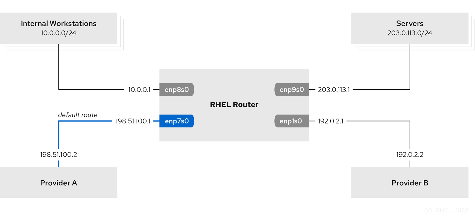
Figure 12.1. Activate a Connection
Prerequisites
-
The RHEL router you want to set up in the procedure has four network interfaces: The
enp7s0interface is connected to the network of provider A. The gateway IP in the provider’s network is198.51.100.2, and the network uses a/30network mask. Theenp1s0interface is connected to the network of provider B. The gateway IP in the provider’s network is192.0.2.2, and the network uses a/30network mask. Theenp8s0interface is connected to the10.0.0.0/24subnet with internal workstations. Theenp9s0interface is connected to the203.0.113.0/24subnet with the company’s servers. Hosts in the internal workstations subnet use10.0.0.1as default gateway. In the procedure, you assign this IP address to theenp8s0network interface of the router. Hosts in the server subnet use203.0.113.1as default gateway. In the procedure, you assign this IP address to theenp9s0network interface of the router. Thefirewalldservice is enabled and active, which is the default.
Procedure
-
Configure the network interface to provider A:
# nmcli connection add type ethernet con-name Provider-A ifname enp7s0 ipv4.method manual ipv4.addresses 198.51.100.1/30 ipv4.gateway 198.51.100.2 ipv4.dns 198.51.100.200 connection.zone external
Thenmcli connection addcommand creates a NetworkManager connection profile. The following list describes the options of the command:type ethernet: Defines that the connection type is Ethernet.con-name connection_name: Sets the name of the profile. Use a meaningful name to avoid confusion.ifname network_device: Sets the network interface.ipv4.method manual: Enables to configure a static IP address.ipv4.addresses IP_address / subnet_mask: Sets the IPv4 addresses and subnet mask.ipv4.gateway IP_address: Sets the default gateway address.ipv4.dns IP_of_DNS_server: Sets the IPv4 address of the DNS server.connection.zone firewalld_zone: Assigns the network interface to the definedfirewalldzone. Note thatfirewalldautomatically enables masquerading interfaces assigned to theexternalzone. Configure the network interface to provider B:# nmcli connection add type ethernet con-name Provider-B ifname enp1s0 ipv4.method manual ipv4.addresses 192.0.2.1/30 ipv4.routes "0.0.0.0/1 192.0.2.2 table=5000, 128.0.0.0/1 192.0.2.2 table=5000" connection.zone external
This command uses theipv4.routesparameter instead ofipv4.gatewayto set the default gateway. This is required to assign the default gateway for this connection to a different routing table (5000) than the default. NetworkManager automatically creates this new routing table when the connection is activated. Thenmcliutility does not support using0.0.0.0/0for the default gateway inipv4.gateway. To work around this problem, the command creates separate routes for both the0.0.0.0/1and128.0.0.0/1subnets, which covers also the full IPv4 address space. Configure the network interface to the internal workstations subnet:# nmcli connection add type ethernet con-name Internal-Workstations ifname enp8s0 ipv4.method manual ipv4.addresses 10.0.0.1/24 ipv4.routes "10.0.0.0/24 src=192.0.2.1 table=5000" ipv4.routing-rules "priority 5 from 10.0.0.0/24 table 5000" connection.zone trusted
This command uses theipv4.routesparameter to add a static route to the routing table with ID5000. This static route for the10.0.0.0/24subnet uses the IP of the local network interface to provider B (192.0.2.1) as next hop. Additionally, the command uses theipv4.routing-rulesparameter to add a routing rule with priority5that routes traffic from the10.0.0.0/24subnet to table5000. Low values have a high priority. Note that the syntax in theipv4.routing-rulesparameter is the same as in anip route addcommand, except thatipv4.routing-rulesalways requires specifying a priority. Configure the network interface to the server subnet:# nmcli connection add type ethernet con-name Servers ifname enp9s0 ipv4.method manual ipv4.addresses 203.0.113.1/24 connection.zone trusted
Verification Steps
-
On a RHEL host in the internal workstation subnet: Install the traceroute package:
# yum install traceroute
-
Use the
tracerouteutility to display the route to a host on the internet:# traceroute redhat.com traceroute to redhat.com (209.132.183.105), 30 hops max, 60 byte packets 1 10.0.0.1 (10.0.0.1) 0.337 ms 0.260 ms 0.223 ms 2 192.0.2.1 (192.0.2.1) 0.884 ms 1.066 ms 1.248 ms The output of the command displays that the router sends packets over
192.0.2.1, which is the network of provider B. On a RHEL host in the server subnet: Install the traceroute package:
# yum install traceroute
Use the
traceroute
utility to display the route to a host on the internet:
# traceroute redhat.com
traceroute to redhat.com (209.132.183.105), 30 hops max, 60 byte packets
1 203.0.113.1 (203.0.113.1) 2.179 ms 2.073 ms 1.944 ms
2 198.51.100.2 (198.51.100.2) 1.868 ms 1.798 ms 1.549 ms
The output of the command displays that the router sends packets over 198.51.100.2, which is the network of provider A.
Troubleshooting Steps
On the RHEL router:
Display the rule list:
# ip rule list
0: from all lookup local
5: from 10.0.0.0/24 lookup 5000
32766: from all lookup main
32767: from all lookup default
Display the routes in table
5000
:
# ip route list table 5000 0.0.0.0/1 via 192.0.2.2 dev enp1s0 proto static metric 100 10.0.0.0/24 dev enp8s0 proto static scope link src 192.0.2.1 metric 102 128.0.0.0/1 via 192.0.2.2 dev enp1s0 proto static metric 100
Display which interfaces are assigned to which firewall zones:
# firewall-cmd --get-active-zones external interfaces: enp1s0 enp7s0 trusted interfaces: enp8s0 enp9s0
Verify that the
external
zone has masquerading enabled:
# firewall-cmd --info-zone=external
external (active)
target: default
icmp-block-inversion: no
interfaces: enp1s0 enp7s0
sources:
services: ssh
ports:
protocols:
masquerade: yes
...
Additional Resources
-
For further details about the
ipv4.*parameters you can set in thenmcli connection addcommand, see the IPv4 settings section in the nm-settings (5) man page. For further details about theconnection.*parameters you can set in thenmcli connection addcommand, see the Connection settings section in the nm-settings (5) man page. For further details about managing NetworkManager connections usingnmcli, see the Connection management commands section in the nmcli (1) man page.
Part III. InfiniBand and RDMA Networking
This part discusses how to set up RDMA, InfiniBand, and IP over InfiniBand network connections.
Chapter 13. Configure InfiniBand and RDMA Networks
13.1. Understanding InfiniBand and RDMA technologies
InfiniBand refers to two distinct things. The first is a physical link-layer protocol for InfiniBand networks. The second is a higher level programming API called the InfiniBand Verbs API. The InfiniBand Verbs API is an implementation of a
remote direct memory access
(
RDMA
) technology.
RDMA provides direct access from the memory of one computer to the memory of another without involving either computer’s operating system. This technology enables high-throughput, low-latency networking with low CPU utilization, which is especially useful in massively parallel computer clusters.
In a typical
IP
data transfer, application X on machine A sends some data to application Y on machine B. As part of the transfer, the kernel on machine B must first receive the data, decode the packet headers, determine that the data belongs to application Y, wake up application Y, wait for application Y to perform a read syscall into the kernel, then it must manually copy the data from the kernel's own internal memory space into the buffer provided by application Y. This process means that most network traffic must be copied across the system's main memory bus at least twice (once when the host adapter uses DMA to put the data into the kernel-provided memory buffer, and again when the kernel moves the data to the application's memory buffer) and it also means the computer must execute a number of context switches to switch between kernel context and application Y context. Both of these things impose extremely high CPU loads on the system when network traffic is flowing at very high rates and can make other tasks to slow down.
RDMA communications differ from normal
IP
communications because they bypass kernel intervention in the communication process, and in the process greatly reduce the CPU overhead normally needed to process network communications. The RDMA protocol allows the host adapter in the machine to know when a packet comes in from the network, which application should receive that packet, and where in the application's memory space it should go. Instead of sending the packet to the kernel to be processed and then copied into the user application's memory, it places the contents of the packet directly in the application's buffer without any further intervention necessary. However, it cannot be accomplished using the standard Berkeley Sockets API that most
IP
networking applications are built upon, so it must provide its own API, the InfiniBand Verbs API, and applications must be ported to this API before they can use RDMA technology directly.
Red Hat Enterprise Linux 7 supports both the InfiniBand hardware and the InfiniBand Verbs API. In addition, there are two additional supported technologies that allow the InfiniBand Verbs API to be utilized on non-InfiniBand hardware:
The Internet Wide Area RDMA Protocol (iWARP)
iWARP is a computer networking protocol that implements remote direct memory access (RDMA) for efficient data transfer over Internet Protocol (IP) networks.
The RDMA over Converged Ethernet (RoCE) protocol, which later renamed to InfiniBand over Ethernet (IBoE).
RoCE is a network protocol that allows remote direct memory access (RDMA) over an Ethernet network.
Prerequisites
Both iWARP and RoCE technologies have a normal
IP
network link layer as their underlying technology, and so the majority of their configuration is actually covered in
Chapter 3,
Configuring IP Networking
. For the most part, once their
IP
networking features are properly configured, their RDMA features are all automatic and will show up as long as the proper drivers for the hardware are installed. The kernel drivers are always included with each kernel Red Hat provides, however the user-space drivers must be installed manually if the InfiniBand package group was not selected at machine install time.
Since Red Hat Enterprise Linux 7.4, all RDMA user-space drivers are merged into the
rdma-core
package. To install all supported iWARP, RoCE or InfiniBand user-space drivers, enter as
root
:
~]# yum install libibverbs
If you are using Priority Flow Control (PFC) and mlx4-based cards, then edit
/etc/modprobe.d/mlx4.conf
to instruct the driver which packet priority is configured for the
“
no-drop
”
service on the Ethernet switches the cards are plugged into and rebuild the
initramfs
to include the modified file. Newer mlx5-based cards auto-negotiate PFC settings with the switch and do not need any module option to inform them of the
“
no-drop
”
priority or priorities.
To set the Mellanox cards to use one or both ports in Ethernet mode, see
Section 13.5.4, “Configuring Mellanox cards for Ethernet operation”
.
With these driver packages installed (in addition to the normal RDMA packages typically installed for any InfiniBand installation), a user should be able to utilize most of the normal RDMA applications to test and see RDMA protocol communication taking place on their adapters. However, not all of the programs included in Red Hat Enterprise Linux 7 properly support iWARP or RoCE/IBoE devices. This is because the connection establishment protocol on iWARP in particular is different than it is on real InfiniBand link-layer connections. If the program in question uses the
librdmacm
connection management library, it handles the differences between iWARP and InfiniBand silently and the program should work. If the application tries to do its own connection management, then it must specifically support iWARP or else it does not work.
13.2. Transferring Data Using RoCE
RDMA over Converged Ethernet (RoCE) is a network protocol that enables remote direct memory access (RDMA) over an Ethernet network. There are two RoCE versions, RoCE v1 and RoCE v2, depending on the network adapter used.
- RoCE v1
-
The
RoCE v1protocol is an Ethernet link layer protocol with ethertype0x8915that enables communication between any two hosts in the same Ethernet broadcast domain. RoCE v1 is the default version for RDMA Connection Manager (RDMA_CM) when using the ConnectX-3 network adapter. - RoCE v2
-
The
RoCE v2protocol exists on top of either the UDP over IPv4 or the UDP over IPv6 protocol. The UDP destination port number4791has been reserved for RoCE v2. Since Red Hat Enterprise Linux 7.5, RoCE v2 is the default version for RDMA_CM when using the ConnectX-3 Pro, ConnectX-4, ConnectX-4 Lx and ConnectX-5 network adapters. Hardware supports bothRoCE v1andRoCE v2. RDMA Connection Manager (RDMA_CM) is used to set up a reliable connection between a client and a server for transferring data. RDMA_CM provides an RDMA transport-neutral interface for establishing connections. The communication is over a specific RDMA device, and data transfers are message-based.Prerequisites
An RDMA_CM session requires one of the following: Both client and server support the same RoCE mode. A client supports RoCE v1 and a server RoCE v2. Since a client determines the mode of the connection, the following cases are possible:- A successful connection:
-
If a client is in RoCE v1 or in RoCE v2 mode depending on the network card and the driver used, the corresponding server must have the same version to create a connection. Also, the connection is successful if a client is in RoCE v1 and a server in RoCE v2 mode.
- A failed connection:
-
If a client is in RoCE v2 and the corresponding server is in RoCE v1, no connection can be established. In this case, update the driver or the network adapter of the corresponding server, see Section 13.2, “Transferring Data Using RoCE”
Table 13.1. RoCE Version Defaults Using RDMA_CM
Client Server Default setting RoCE v1 RoCE v1 Connection RoCE v1 RoCE v2 Connection RoCE v2 RoCE v2 Connection RoCE v2 RoCE v1 No connection That RoCE v2 on the client and RoCE v1 on the server are not compatible. To resolve this issue, force both the server and client-side environment to communicate over RoCE v1. This means to force hardware that supports RoCE v2 to use RoCE v1:Procedure 13.1. Changing the Default RoCE Mode When the Hardware Is Already Running in Roce v2
-
Change into the
/sys/kernel/config/rdma_cmdirectory to et the RoCE mode:~]#
Enter thecd /sys/kernel/config/rdma_cmibstatcommand with an Ethernet network device to display the status. For example, for mlx5_0 :~]$
Create a directory for the mlx5_0 device:ibstatmlx5_0 CA 'mlx5_0' CA type: MT4115 Number of ports: 1 Firmware version: 12.17.1010 Hardware version: 0 Node GUID: 0x248a0703004bf0a4 System image GUID: 0x248a0703004bf0a4 Port 1: State: Active Physical state: LinkUp Rate: 40 Base lid: 0 LMC: 0 SM lid: 0 Capability mask: 0x04010000 Port GUID: 0x268a07fffe4bf0a4 Link layer: Ethernet~]#
Display the RoCE mode in themkdirmlx5_0default_roce_modefile in the tree format:~]#
cdmlx5_0~]$ tree └── ports └── 1 ├── default_roce_mode └── default_roce_tos~]$
Change the default RoCE mode:cat /sys/kernel/config/rdma_cm/mlx5_0/ports/1/default_roce_modeRoCE v2~]#
View the changes:echo "RoCE v1" > /sys/kernel/config/rdma_cm/mlx5_0/ports/1/default_roce_mode~]$
cat /sys/kernel/config/rdma_cm/mlx5_0/ports/1/default_roce_modeRoCE v1
13.3. Configuring Soft-RoCE
RoCE can be implemented both in the hardware and in the software. Soft-RoCE is the software implementation of the RDMA transport.
Prerequisites
Since Red Hat Enterprise Linux 7.4, the Soft-RoCE driver is already merged into the kernel. The user-space driver also is merged into the
rdma-core
package. Soft-RoCE is also known as RXE. To start, stop and configure RXE, use the
rxe_cfg
script. To view options for
rxe_cfg
, enter
rxe_cfg help
.
Procedure 13.2. Configuring Soft-RoCE
-
As the
rootuser, enter the following command to display the current configuration status of RXE:~]#
To load the RXE kernel module and start RXE, enter asrxe_cfgrdma_rxe module not loaded Name Link Driver Speed NMTU IPv4_addr RDEV RMTU igb_1yesigb mlx4_1 no mlx4_en mlx4_2 no mlx4_enroot:~]#
Optionally, to verify that the RXE kernel module is loaded, enter:rxe_cfg startName Link Driver Speed NMTU IPv4_addr RDEV RMTU igb_1yesigb mlx4_1 no mlx4_en mlx4_2 no mlx4_en~]#
lsmod |grep rdma_rxerdma_rxe 111129 0 ip6_udp_tunnel 12755 1 rdma_rxe udp_tunnel 14423 1 rdma_rxe ib_core 236827 15 rdma_cm,ib_cm,iw_cm,rpcrdma,mlx4_ib,ib_srp,ib_ucm,ib_iser,ib_srpt,ib_umad,ib_uverbs,rdma_rxe,rdma_ucm,ib_ipoib,ib_isert Before adding a new RXE device over an Ethernet interface, the corresponding interface should be opened and has a valid IP address assigned. To add a new RXE device, for example igb_1:~]#
rxe_cfg add igb_1~]#
The rxe0 in the RDEV column indicates that rxe is enabled for the igb_1 device. To verify the status of an RXE device, use therxe_cfg statusName Link Driver Speed NMTU IPv4_addr RDEV RMTU igb_1 yes igb rxe0 1024 (3) mlx4_1 no mlx4_en mlx4_2 no mlx4_enibv_devicescommand:~]#
Alternatively, enter theibv_devicesdevice node GUID ------ ---------------- mlx4_0 0002c90300b3cff0 rxe0 a2369ffffe018294ibstatfor a detailed status:~]#
ibstatrxe0 CA 'rxe0' CA type: Number of ports: 1 Firmware version: Hardware version: Node GUID: 0xa2369ffffe018294 System image GUID: 0x0000000000000000 Port 1: State: Active Physical state: LinkUp Rate: 2.5 Base lid: 0 LMC: 0 SM lid: 0 Capability mask: 0x00890000 Port GUID: 0xa2369ffffe018294 Link layer: Ethernet
Removing an RXE device
If you want to remove an RXE device, enter:
~]# rxe_cfg remove igb_1
Verifying Connectivity of an RXE device
The following examples show how to verify connectivity of an RXE device on the server and client side.
Example 13.1. Verifying Connectivity of an RXE device on the Server Side
~]$ ibv_rc_pingpong -d rxe0 -g 0
local address: LID 0x0000, QPN 0x000012, PSN 0xe2965f, GID fe80::290:faff:fe29:486a
remote address: LID 0x0000, QPN 0x000011, PSN 0x4bf206, GID fe80::290:faff:fe29:470a
8192000 bytes in 0.05 seconds = 1244.06 Mbit/sec
1000 iters in 0.05 seconds = 52.68 usec/iter
Example 13.2. Verifying Connectivity of an RXE device on the Client Side
~]$ ibv_rc_pingpong -d rxe0 -g 0 172.31.40.4
local address: LID 0x0000, QPN 0x000011, PSN 0x4bf206, GID fe80::290:faff:fe29:470a
remote address: LID 0x0000, QPN 0x000012, PSN 0xe2965f, GID fe80::290:faff:fe29:486a
8192000 bytes in 0.05 seconds = 1245.72 Mbit/sec
1000 iters in 0.05 seconds = 52.61 usec/iter
13.4. InfiniBand and RDMA related software packages
Because RDMA applications are so different from Berkeley Sockets based applications, and from normal
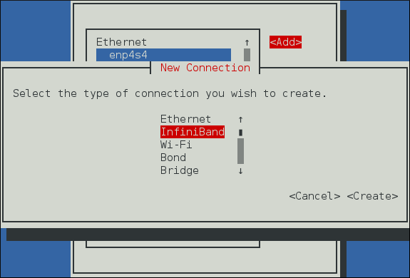

IP
networking, most applications that are used on an
IP
network cannot be used directly on an RDMA network. Red Hat Enterprise Linux 7 comes with a number of different software packages for RDMA network administration, testing and debugging, high level software development APIs, and performance analysis.
In order to utilize these networks, some or all of these packages need to be installed (this list is not exhaustive, but does cover the most important packages related to RDMA).
Required packages:
-
rdma— responsible for kernel initialization of the RDMA stack.libibverbs— provides the InfiniBand Verbs API.opensm— subnet manager (only required on one machine, and only if there is no subnet manager active on the fabric).user space driver for installed hardware— one or more of: infinipath-psm , libcxgb3 , libcxgb4 , libehca , libipathverbs , libmthca , libmlx4 , libmlx5 , libnes , and libocrdma . Note that libehca is only available for IBM Power Systems servers.Recommended packages:
-
librdmacm , librdmacm-utils , and ibacm— Connection management library that is aware of the differences between InfiniBand, iWARP, and RoCE and is able to properly open connections across all of these hardware types, some simple test programs for verifying the operation of the network, and a caching daemon that integrates with the library to make remote host resolution faster in large clusters.libibverbs-utils— Simple Verbs based programs for querying the installed hardware and verifying communications over the fabric.infiniband-diags and ibutils— Provide a number of useful debugging tools for InfiniBand fabric management. These provide only very limited functionality on iWARP or RoCE as most of the tools work at the InfiniBand link layer, not the Verbs API layer.perftest and qperf— Performance testing applications for various types of RDMA communications.Optional packages:
These packages are available in the Optional channel. Before installing packages from the Optional channel, see Scope of Coverage Details . Information on subscribing to the Optional channel can be found in the Red Hat Knowledgebase solution How to access Optional and Supplementary channels .dapl , dapl-devel , and dapl-utils— Provide a different API for RDMA than the Verbs API. There is both a runtime component and a development component to these packages.openmpi , mvapich2 , and mvapich2-psm— MPI stacks that have the ability to use RDMA communications. User-space applications writing to these stacks are not necessarily aware that RDMA communications are taking place.13.5. Configuring the Base RDMA Subsystem
Startup of therdmaservice is automatic. When RDMA capable hardware, whether InfiniBand or iWARP or RoCE/IBoE is detected, udev instructssystemdto start therdmaservice.~]#
systemctl status rdma● rdma.service - Initialize the iWARP/InfiniBand/RDMA stack in the kernel Loaded: loaded (/usr/lib/systemd/system/rdma.service; disabled; vendor preset: disabled) Active: inactive (dead) Docs: file:/etc/rdma/rdma.confUsers need not enable therdmaservice, but they can if they want to force it on all the time. To do that, enter the following command as root:~]#
systemctl enable rdma13.5.1. Configuration of the rdma.conf file
Therdmaservice reads/etc/rdma/rdma.confto find out which kernel-level and user-level RDMA protocols the administrator wants to be loaded by default. Users should edit this file to turn various drivers on or off. The various drivers that can be enabled and disabled are:IPoIB— This is anIPnetwork emulation layer that allowsIPapplications to run over InfiniBand networks.SRP— This is the SCSI Request Protocol. It allows a machine to mount a remote drive or drive array that is exported through theSRPprotocol on the machine as though it were a local hard disk.SRPT— This is the target mode, or server mode, of theSRPprotocol. This loads the kernel support necessary for exporting a drive or drive array for other machines to mount as though it were local on their machine. Further configuration of the target mode support is required before any devices will actually be exported. See the documentation in the targetd and targetcli packages for further information.ISER— This is a low-level driver for the general iSCSI layer of the Linux kernel that provides transport over InfiniBand networks for iSCSI devices.RDS— This is the Reliable Datagram Service in the Linux kernel. It is not enabled in Red Hat Enterprise Linux 7 kernels and so cannot be loaded.13.5.2. Usage of 70-persistent-ipoib.rules
The rdma package provides the file/etc/udev.d/rules.d/70-persistent-ipoib.rules. This udev rules file is used to rename IPoIB devices from their default names (such asib0andib1) to more descriptive names. Users must edit this file to change how their devices are named. First, find out the GUID address for the device to be renamed:~]$
Immediately afterip link show ib08: ib0: >BROADCAST,MULTICAST,UP,LOWER_UP< mtu 65520 qdisc pfifo_fast state UP mode DEFAULT qlen 256 link/infiniband 80:00:02:00:fe:80:00:00:00:00:00:00:f4:52:14:03:00:7b:cb:a1 brd 00:ff:ff:ff:ff:12:40:1b:ff:ff:00:00:00:00:00:00:ff:ff:ff:fflink/infinibandis the 20 byte hardware address for the IPoIB interface. The final 8 bytes of the address, marked in bold above, is all that is required to make a new name. Users can make up whatever naming scheme suits them. For example, use a device_fabric naming convention such asmlx4_ib0if amlx4device is connected to anib0subnet fabric. The only thing that is not recommended is to use the standard names, likeib0orib1, as these can conflict with the kernel assigned automatic names. Next, add an entry in the rules file. Copy the existing example in the rules file, replace the 8 bytes in theATTR{address}entry with the highlighted 8 bytes from the device to be renamed, and enter the new name to be used in theNAMEfield.13.5.3. Relaxing memlock restrictions for users
RDMA communications require that physical memory in the computer be pinned (meaning that the kernel is not allowed to swap that memory out to a paging file in the event that the overall computer starts running short on available memory). Pinning memory is normally a very privileged operation. In order to allow users other thanrootto run large RDMA applications, it will likely be necessary to increase the amount of memory that non-rootusers are allowed to pin in the system. This is done by adding a file in the/etc/security/limits.d/directory with contents such as the following: ~]$more /etc/security/limits.d/rdma.conf# configuration for rdma tuning * soft memlock unlimited * hard memlock unlimited # rdma tuning end13.5.4. Configuring Mellanox cards for Ethernet operation
Certain hardware from Mellanox is capable of running in either InfiniBand or Ethernet mode. These cards generally default to InfiniBand. Users can set the cards to Ethernet mode. There is currently support for setting the mode only on ConnectX family hardware (which uses either the mlx5 or mlx4 driver). To configure Mellanox mlx5 cards, use the mstconfig program from the mstflint package. For more details, see the Configuring Mellanox mlx5 cards in Red Hat Enterprise Linux 7 Knowledge Base article on the Red Hat Customer Portal. To configure Mellanox mlx4 cards, use mstconfig to set the port types on the card as described in the Knowledge Base article . If mstconfig does not support your card, edit the/etc/rdma/mlx4.conffile and follow the instructions in that file to set the port types properly for RoCE/IBoE usage. In this case is also necessary to rebuild theinitramfsto make sure the updated port settings are copied into theinitramfs. Once the port type has been set, if one or both ports are set to Ethernet and mstconfig was not used to set the port types, then users might see this message in their logs:mlx4_core 0000:05:00.0: Requested port type for port 1 is not supported on this HCA
This is normal and does not affect operation. The script responsible for setting the port type has no way of knowing when the driver has finished switching port 2 to the requested type internally, and from the time that the script issues a request for port 2 to switch until that switch is complete, the attempts to set port 1 to a different type get rejected. The script retries until the command succeeds or until a timeout has passed indicating that the port switch never completed.13.5.5. Connecting to a Remote Linux SRP Target
The SCSI RDMA Protocol (SRP) is a network protocol that enables a system to use RDMA to access SCSI devices that are attached to another system. To allow an SRP initiator to connect an SRP target on the SRP target side, you must add an access control list (ACL) entry for the host channel adapter (HCA) port used in the initiator. ACL IDs for HCA ports are not unique. The ACL IDs depend on the GID format of the HCAs. HCAs that use the same driver, for exampleib_qib, can have different format of GIDs. The ACL ID also depends on how you initiate the connection request.Connecting to a Remote Linux SRP Target: High-Level Overview
-
Prepare the target side: Create storage back end. For example get the /dev/sdc1 partition:
/> /backstores/block create vol1 /dev/sdc1
Create an SRP target:/> /srpt create 0xfe80000000000000001175000077dd7e
Create a LUN based on the back end created in step a:/> /srpt/ib.fe80000000000000001175000077dd7e/luns create /backstores/block/vol1
Create a Node ACL for the remote SRP client:/> /srpt/ib.fe80000000000000001175000077dd7e/acls create 0x7edd770000751100001175000077d708
Note that the Node ACL is different forsrp_daemonandibsrpdm. Initiate an SRP connection withsrp_daemonoribsrpdmfor the client side: [root@initiator]# srp_daemon -e -n -i qib0 -p 1 -R 60 & [root@initiator]# ibsrpdm -c -d /dev/infiniband/umad0 > /sys/class/infiniband_srp/srp-qib0-1/add_target Optional. It is recommended to verify the SRP connection with different tools, such aslsscsiordmesg.
Procedure 13.3. Connecting to a Remote Linux SRP Target with srp_daemon or ibsrpdm
-
Use the
ibstatcommand on the target to determine theStateandPort GUIDvalues. The HCA must be inActivestate. The ACL ID is based on thePort GUID: [root@target]#ibstatCA 'qib0' CA type: InfiniPath_QLE7342 Number of ports: 1 Firmware version: Hardware version: 2 Node GUID: 0x001175000077dd7e System image GUID: 0x001175000077dd7e Port 1: State:ActivePhysical state: LinkUp Rate: 40 Base lid: 1 LMC: 0 SM lid: 1 Capability mask: 0x0769086a Port GUID:0x001175000077dd7eLink layer: InfiniBand Get the SRP target ID, which is based on the GUID of the HCA port. Note that you need a dedicated disk partition as a back end for a SRP target, for example/dev/sdc1. The following command replaces the default prefix of fe80, removes the colon, and adds the new prefix to the remainder of the string: [root@target]#ibstatus | grep ' <default-gid> ' | sed -e 's/ <default-gid> ://' -e 's/://g' | grep 001175000077dd7efe80000000000000001175000077dd7e Use thetargetclitool to create the LUN vol1 on the block device, create an SRP target, and export the LUN: [root@target]#targetcli/>/backstores/block create vol1 /dev/sdc1Created block storage object vol1 using /dev/sdc1. />/srpt create 0xfe80000000000000001175000077dd7eCreated target ib.fe80000000000000001175000077dd7e. />/srpt/ib.fe80000000000000001175000077dd7e/luns create /backstores/block/vol1Created LUN 0. />ls /o- / ............................................................................. [...] o- backstores .................................................................. [...] | o- block ...................................................... [Storage Objects: 1] | | o- vol1 ............................... [/dev/sdc1 (77.8GiB) write-thru activated] | o- fileio ..................................................... [Storage Objects: 0] | o- pscsi ...................................................... [Storage Objects: 0] | o- ramdisk .................................................... [Storage Objects: 0] o- iscsi ................................................................ [Targets: 0] o- loopback ............................................................. [Targets: 0] o- srpt ................................................................. [Targets: 1] o- ib.fe80000000000000001175000077dd7e ............................... [no-gen-acls] o- acls ................................................................ [ACLs: 0] o- luns ................................................................ [LUNs: 1] o- lun0 ............................................... [block/vol1 (/dev/sdc1)] Use theibstatcommand on the initiator to check if the state isActiveand determine thePort GUID: [root@initiator]#ibstatCA 'qib0' CA type: InfiniPath_QLE7342 Number of ports: 1 Firmware version: Hardware version: 2 Node GUID: 0x001175000077d708 System image GUID: 0x001175000077d708 Port 1: State:ActivePhysical state: LinkUp Rate: 40 Base lid: 2 LMC: 0 SM lid: 1 Capability mask: 0x07690868 Port GUID:0x001175000077d708Link layer: InfiniBand Use the following command to scan without connecting to a remote SRP target. The target GUID shows that the initiator had found remote target. The ID string shows that the remote target is a Linux software target (ib_srpt.ko). [root@initiator]#srp_daemon -a -oIO Unit Info: port LID: 0001 port GID:fe80000000000000001175000077dd7echange ID: 0001 max controllers: 0x10 controller[ 1] GUID:001175000077dd7evendor ID: 000011 device ID: 007322 IO class : 0100 ID:Linux SRP targetservice entries: 1 service[ 0]: 001175000077dd7e / SRP.T10:001175000077dd7e To verify the SRP connection, use thelsscsicommand to list SCSI devices and compare thelsscsioutput before and after the initiator connects to target. [root@initiator]#lsscsi[0:0:10:0] disk IBM-ESXS ST9146803SS B53C /dev/sda To connect to a remote target without configuring a valid ACL for the initiator port, which is expected to fail, use the following commands forsrp_daemonoribsrpdm: [root@initiator]#srp_daemon -e -n -i qib0 -p 1 -R 60 &[1] 4184 [root@initiator]#ibsrpdm -c -d /dev/infiniband/umad0 > /sys/class/infiniband_srp/srp-qib0-1/add_targetThe output of thedmesgshows why the SRP connection operation failed. In a later step, thedmesgcommand on the target side is used to make the situation clear. [root@initiator]#dmesg -c[ 1230.059652] scsi host5: ib_srp: REJ received [ 1230.059659] scsi host5: ib_srp: SRP LOGIN fromfe80:0000:0000:0000:0011:7500:0077:d708to fe80:0000:0000:0000:0011:7500:0077:dd7e REJECTED, reason0x00010006[ 1230.073792] scsi host5: ib_srp: Connection 0/2 failed [ 1230.078848] scsi host5: ib_srp: Sending CM DREQ failed Because of failed LOGIN, the output of thelsscsicommand is the same as in the earlier step. [root@initiator]#lsscsi[0:0:10:0] disk IBM-ESXS ST9146803SS B53C /dev/sda Using thedmesgon the target side (ib_srpt.ko) provides an explanation of why LOGIN failed. Also, the output contains the valid ACL ID provided bysrp_daemon:0x7edd770000751100001175000077d708. [root@target]#dmesg[ 1200.303001] ib_srpt Received SRP_LOGIN_REQ with i_port_id 0x7edd770000751100:0x1175000077d708, t_port_id 0x1175000077dd7e:0x1175000077dd7e and it_iu_len 260 on port 1 (guid=0xfe80000000000000:0x1175000077dd7e)[ 1200.322207] ib_srpt Rejected login because no ACL has been configured yet for initiator 0x7edd770000751100001175000077d708. -
Use the
targetclitool to add a valid ACL: [root@target]#targetclitargetcli shell version 2.1.fb41 For help on commands, type 'help'. /> /srpt/ib.fe80000000000000001175000077dd7e/acls create0x7edd770000751100001175000077d708Created Node ACL for ib.7edd770000751100001175000077d708 Created mapped LUN 0. Verify the SRP LOGIN operation: Wait for 60 seconds to allowsrp_daemonto re-try logging in: [root@initiator]#sleep 60 -
Verify the SRP LOGIN operation: [root@initiator]#
lsscsi[0:0:10:0] disk IBM-ESXS ST9146803SS B53C /dev/sda[7:0:0:0] disk LIO-ORG vol1 4.0 /dev/sdb -
For a kernel log of SRP target discovery, use: [root@initiator]#
dmesg -c[ 1354.182072] scsi host7: SRP.T10:001175000077DD7E [ 1354.187258] scsi 7:0:0:0: Direct-Access LIO-ORG vol1 4.0 PQ: 0 ANSI: 5 [ 1354.208688] scsi 7:0:0:0: alua: supports implicit and explicit TPGS [ 1354.215698] scsi 7:0:0:0: alua: port group 00 rel port 01 [ 1354.221409] scsi 7:0:0:0: alua: port group 00 state A non-preferred supports TOlUSNA [ 1354.229147] scsi 7:0:0:0: alua: Attached [ 1354.233402] sd 7:0:0:0: Attached scsi generic sg1 type 0 [ 1354.233694] sd 7:0:0:0: [sdb] 163258368 512-byte logical blocks: (83.5 GB/77.8 GiB) [ 1354.235127] sd 7:0:0:0: [sdb] Write Protect is off [ 1354.235128] sd 7:0:0:0: [sdb] Mode Sense: 43 00 00 08 [ 1354.235550] sd 7:0:0:0: [sdb] Write cache: disabled, read cache: enabled, doesn't support DPO or FUA [ 1354.255491] sd 7:0:0:0: [sdb] Attached SCSI disk [ 1354.265233] scsi host7: ib_srp: new target: id_ext 001175000077dd7e ioc_guid 001175000077dd7e pkey ffff service_id 001175000077dd7e sgid fe80:0000:0000:0000:0011:7500:0077:d708 dgid fe80:0000:0000:0000:0011:7500:0077:dd7e
-
-
13.6. Configuring the Subnet Manager
13.6.1. Determining Necessity
Most InfiniBand switches come with an embedded subnet manager. However, if a more up to date subnet manager is required than the one in the switch firmware, or if more complete control than the switch manager allows is required, Red Hat Enterprise Linux 7 includes the
opensm
subnet manager. All InfiniBand networks
must
have a subnet manager running for the network to function. This is true even when doing a simple network of two machines with no switch and the cards are plugged in back to back, a subnet manager is required for the link on the cards to come up. It is possible to have more than one, in which case one will act as controller, and any other subnet managers will act as ports that will take over should the controller subnet manager fail.
13.6.2. Configuring the opensm main configuration file
The
opensm
program keeps its main configuration file in
/etc/rdma/opensm.conf
. Users may edit this file at any time and edits will be kept on upgrade. There is extensive documentation of the options in the file itself. However, for the two most common edits needed, setting the GUID to bind to and the PRIORITY to run with, it is highly recommended that the
opensm.conf
file is not edited but instead edit
/etc/sysconfig/opensm
. If there are no edits to the base
/etc/rdma/opensm.conf
file, it will get upgraded whenever the
opensm
package is upgraded. As new options are added to this file regularly, this makes it easier to keep the current configuration up to date. If the
opensm.conf
file has been changed, then on upgrade, it might be necessary to merge new options into the edited file.
13.6.3. Configuring the opensm startup options
The options in the
/etc/sysconfig/opensm
file control how the subnet manager is actually started, as well as how many copies of the subnet manager are started. For example, a dual port InfiniBand card, with each port plugged into physically separate networks, will need a copy of the subnet manager running on each port. The
opensm
subnet manager will only manage one subnet per instance of the application and must be started once for each subnet that needs to be managed. In addition, if there is more than one
opensm
server, then set the priorities on each server to control which are to be ports and which are to be controller.
The file
/etc/sysconfig/opensm
is used to provide a simple means to set the priority of the subnet manager and to control which GUID the subnet manager binds to. There is an extensive explanation of the options in the
/etc/sysconfig/opensm
file itself. Users need only read and follow the directions in the file itself to enable failover and multifabric operation of
opensm
.
13.6.4. Creating a P_Key definition
By default,
opensm.conf
looks for the file
/etc/rdma/partitions.conf
to get a list of partitions to create on the fabric. All fabrics must contain the
0x7fff
subnet, and all switches and all hosts must belong to that fabric. Any other partition can be created in addition to that, and all hosts and all switches do not have to be members of these additional partitions. This allows an administrator to create subnets akin to Ethernet’s VLANs on InfiniBand fabrics. If a partition is defined with a given speed, such as 40 Gbps, and there is a host on the network unable to do 40 Gbps, then that host will be unable to join the partition even if it has permission to do so as it will be unable to match the speed requirements, therefore it is recommended that the speed of a partition be set to the slowest speed of any host with permission to join the partition. If a faster partition for some subset of hosts is required, create a different partition with the higher speed.
The following partition file would result in a default
0x7fff
partition at a reduced speed of 10 Gbps, and a partition of
0x0002
with a speed of 40 Gbps:
~]$ more /etc/rdma/partitions.conf
# For reference:
# IPv4 IANA reserved multicast addresses:
# http://www.iana.org/assignments/multicast-addresses/multicast-addresses.txt
# IPv6 IANA reserved multicast addresses:
# http://www.iana.org/assignments/ipv6-multicast-addresses/ipv6-multicast-addresses.xml
# mtu =
# 1 = 256
# 2 = 512
# 3 = 1024
# 4 = 2048
# 5 = 4096
# rate =
# 2 = 2.5 GBit/s
# 3 = 10 GBit/s
# 4 = 30 GBit/s
# 5 = 5 GBit/s
# 6 = 20 GBit/s
# 7 = 40 GBit/s
# 8 = 60 GBit/s
# 9 = 80 GBit/s
# 10 = 120 GBit/s
Default=0x7fff, rate=3, mtu=4, scope=2, defmember=full:
ALL, ALL_SWITCHES=full;
Default=0x7fff, ipoib, rate=3, mtu=4, scope=2:
mgid=ff12:401b::ffff:ffff # IPv4 Broadcast address
mgid=ff12:401b::1 # IPv4 All Hosts group
mgid=ff12:401b::2 # IPv4 All Routers group
mgid=ff12:401b::16 # IPv4 IGMP group
mgid=ff12:401b::fb # IPv4 mDNS group
mgid=ff12:401b::fc # IPv4 Multicast Link Local Name Resolution group
mgid=ff12:401b::101 # IPv4 NTP group
mgid=ff12:401b::202 # IPv4 Sun RPC
mgid=ff12:601b::1 # IPv6 All Hosts group
mgid=ff12:601b::2 # IPv6 All Routers group
mgid=ff12:601b::16 # IPv6 MLDv2-capable Routers group
mgid=ff12:601b::fb # IPv6 mDNS group
mgid=ff12:601b::101 # IPv6 NTP group
mgid=ff12:601b::202 # IPv6 Sun RPC group
mgid=ff12:601b::1:3 # IPv6 Multicast Link Local Name Resolution group
ALL=full, ALL_SWITCHES=full;
ib0_2=0x0002, rate=7, mtu=4, scope=2, defmember=full:
ALL, ALL_SWITCHES=full;
ib0_2=0x0002, ipoib, rate=7, mtu=4, scope=2:
mgid=ff12:401b::ffff:ffff # IPv4 Broadcast address
mgid=ff12:401b::1 # IPv4 All Hosts group
mgid=ff12:401b::2 # IPv4 All Routers group
mgid=ff12:401b::16 # IPv4 IGMP group
mgid=ff12:401b::fb # IPv4 mDNS group
mgid=ff12:401b::fc # IPv4 Multicast Link Local Name Resolution group
mgid=ff12:401b::101 # IPv4 NTP group
mgid=ff12:401b::202 # IPv4 Sun RPC
mgid=ff12:601b::1 # IPv6 All Hosts group
mgid=ff12:601b::2 # IPv6 All Routers group
mgid=ff12:601b::16 # IPv6 MLDv2-capable Routers group
mgid=ff12:601b::fb # IPv6 mDNS group
mgid=ff12:601b::101 # IPv6 NTP group
mgid=ff12:601b::202 # IPv6 Sun RPC group
mgid=ff12:601b::1:3 # IPv6 Multicast Link Local Name Resolution group
ALL=full, ALL_SWITCHES=full;
13.6.5. Enabling opensm
Users need to enable the
opensm
service as it is not enabled by default when installed. Issue the following command as
root
:
~]# systemctl enable opensm
13.7. Testing Early InfiniBand RDMA operation
Note
This section applies only to InfiniBand devices. Since iWARP and RoCE/IBoE devices are
IP
based devices, users should proceed to the section on testing RDMA operations once IPoIB has been configured and the devices have
IP
addresses.
Once the
rdma
service is enabled, and the
opensm
service (if needed) is enabled, and the proper user-space library for the specific hardware has been installed, user space
rdma
operation should be possible. Simple test programs from the
libibverbs-utils
package are helpful in determining that RDMA operations are working properly. The
ibv_devices
program will show which devices are present in the system and the
ibv_devinfo
command will give detailed information about each device. For example:
~]$Theibv_devicesdevice node GUID ------ ---------------- mlx4_0 0002c903003178f0 mlx4_1 f4521403007bcba0 ~]$ibv_devinfo -d mlx4_1hca_id: mlx4_1 transport: InfiniBand (0) fw_ver: 2.30.8000 node_guid: f452:1403:007b:cba0 sys_image_guid: f452:1403:007b:cba3 vendor_id: 0x02c9 vendor_part_id: 4099 hw_ver: 0x0 board_id: MT_1090120019 phys_port_cnt: 2 port: 1 state: PORT_ACTIVE (4) max_mtu: 4096 (5) active_mtu: 2048 (4) sm_lid: 2 port_lid: 2 port_lmc: 0x01 link_layer: InfiniBand port: 2 state: PORT_ACTIVE (4) max_mtu: 4096 (5) active_mtu: 4096 (5) sm_lid: 0 port_lid: 0 port_lmc: 0x00 link_layer: Ethernet~]$ ibstat mlx4_1CA 'mlx4_1' CA type: MT4099 Number of ports: 2 Firmware version: 2.30.8000 Hardware version: 0 Node GUID: 0xf4521403007bcba0 System image GUID: 0xf4521403007bcba3 Port 1: State: Active Physical state: LinkUp Rate: 56 Base lid: 2 LMC: 1 SM lid: 2 Capability mask: 0x0251486a Port GUID: 0xf4521403007bcba1 Link layer: InfiniBand Port 2: State: Active Physical state: LinkUp Rate: 40 Base lid: 0 LMC: 0 SM lid: 0 Capability mask: 0x04010000 Port GUID: 0xf65214fffe7bcba2 Link layer: Ethernet
ibv_devinfo
and
ibstat
commands output slightly different information (such as port MTU exists in
ibv_devinfo
but not in
ibstat
output, and the Port GUID exists in
ibstat
output but not in
ibv_devinfo
output), and a few things are named differently (for example, the Base
local identifier
(
LID
) in
ibstat
output is the same as the
port_lid
output of
ibv_devinfo
)
Simple ping programs, such as
ibping
from the
infiniband-diags
package, can be used to test RDMA connectivity. The
ibping
program uses a client-server model. You must first start an
ibping
server on one machine, then run
ibping
as a client on another machine and tell it to connect to the
ibping
server. Since we are wanting to test the base RDMA capability, we need to use an RDMA specific address resolution method instead of
IP
addresses for specifying the server.
On the server machine, the user can use the
ibv_devinfo
and
ibstat
commands to print out the
port_lid
(or Base lid) and the Port GUID of the port they want to test (assuming port 1 of the above interface, the
port_lid
/
Base LID
is
2
and Port GUID is
0xf4521403007bcba1
)). Then start
ibping
with the necessary options to bind specifically to the card and port to be tested, and also specifying
ibping
should run in server mode. You can see the available options to
ibping
by passing
-?
or
--help
, but in this instance we will need either the
-S
or
--Server
option and for binding to the specific card and port we will need either
-C
or
--Ca
and
-P
or
--Port
. Note: port in this instance does not denote a network port number, but denotes the physical port number on the card when using a multi-port card. To test connectivity to the RDMA fabric using, for example, the second port of a multi-port card, requires telling
ibping
to bind to port
2
on the card. When using a single port card, or testing the first port on a card, this option is not needed. For example:
~]$ ibping -S -C mlx4_1 -P 1
Then change to the client machine and run
ibping
. Make note of either the port GUID of the port the server
ibping
program is bound to, or the
local identifier
(
LID
) of the port the server
ibping
program is bound to. Also, take note which card and port in the client machine is physically connected to the same network as the card and port that was bound to on the server. For example, if the second port of the first card on the server was bound to, and that port is connected to a secondary RDMA fabric, then on the client specify whichever card and port are necessary to also be connected to that secondary fabric. Once these things are known, run the
ibping
program as a client and connect to the server using either the port LID or GUID that was collected on the server as the address to connect to. For example:
~]$ ibping -c 10000 -f -C mlx4_0 -P 1 -L 2
--- rdma-host.example.com.(none) (Lid 2) ibping statistics ---
10000 packets transmitted, 10000 received, 0% packet loss, time 816 ms
rtt min/avg/max = 0.032/0.081/0.446 ms
~]$ ibping -c 10000 -f -C mlx4_0 -P 1 -G 0xf4521403007bcba1 \
--- rdma-host.example.com.(none) (Lid 2) ibping statistics ---
10000 packets transmitted, 10000 received, 0% packet loss, time 769 ms
rtt min/avg/max = 0.027/0.076/0.278 ms
This outcome verifies that end to end RDMA communications are working for user space applications.
The following error may be encountered:
~]$ ibv_devinfo
libibverbs: Warning: no userspace device-specific driver found for /sys/class/infiniband_verbs/uverbs0
No IB devices found
This error indicates that the necessary user-space library is not installed. The administrator will need to install one of the user-space libraries (as appropriate for their hardware) listed in section
Section 13.4, “InfiniBand and RDMA related software packages”
. On rare occasions, this can happen if a user installs the wrong arch type for the driver or for
libibverbs
. For example, if
libibverbs
is of arch
x86_64
, and
libmlx4
is installed but is of type
i686
, then this error can result.
Many sample applications prefer to use host names or addresses instead of LIDs to open communication between the server and client. For those applications, it is necessary to set up IPoIB before attempting to test end-to-end RDMA communications. The
ibping
application is unusual in that it will accept simple LIDs as a form of addressing, and this allows it to be a simple test that eliminates possible problems with IPoIB addressing from the test scenario and therefore gives us a more isolated view of whether or not simple RDMA communications are working.
13.8. Configuring IPoIB
13.8.1. Understanding the role of IPoIB
As mentioned in
Section 1.1, “Comparing IP to non-IP Networks”
, most networks are
IP
networks. InfiniBand is not. The role of IPoIB is to provide an
IP
network emulation layer on top of InfiniBand RDMA networks. This allows existing applications to run over InfiniBand networks unmodified. However, the performance of those applications is considerably lower than if the application were written to use RDMA communication natively. Since most InfiniBand networks have some set of applications that really must get all of the performance they can out of the network, and then some other applications for which a degraded rate of performance is acceptable if it means that the application does not need to be modified to use RDMA communications, IPoIB is there to allow those less critical applications to run on the network as they are.
Because both iWARP and RoCE/IBoE networks are actually
IP
networks with RDMA layered on top of their
IP
link layer, they have no need of IPoIB. As a result, the kernel will refuse to create any IPoIB devices on top of iWARP or RoCE/IBoE RDMA devices.
13.8.2. Understanding IPoIB communication modes
IPoIB devices can be configured to run in either datagram or connected mode. The difference is in what type of queue pair the IPoIB layer attempts to open with the machine at the other end of the communication. For datagram mode, an unreliable, disconnected queue pair is opened. For connected mode, a reliable, connected queue pair is opened.
When using datagram mode, the unreliable, disconnected queue pair type does not allow any packets larger than the InfiniBand link-layer’s MTU. The IPoIB layer adds a 4 byte IPoIB header on top of the
IP
packet being transmitted. As a result, the IPoIB MTU must be 4 bytes less than the InfiniBand link-layer MTU. As 2048 is a common InfiniBand link-layer MTU, the common IPoIB device MTU in datagram mode is 2044.
When using connected mode, the reliable, connected queue pair type allows messages that are larger than the InfiniBand link-layer MTU and the host adapter handles packet segmentation and reassembly at each end. As a result, there is no size limit imposed on the size of IPoIB messages that can be sent by the InfiniBand adapters in connected mode. However, there is still the limitation that an
IP
packet only has a 16 bit size field, and is therefore limited to
65535
as the maximum byte count. The maximum allowed MTU is actually smaller than that because we have to account for various TCP/IP headers that must also fit in that size. As a result, the IPoIB MTU in connected mode is capped at
65520
in order to make sure there is sufficient room for all needed
TCP
headers.
The connected mode option generally has higher performance, but it also consumes more kernel memory. Because most systems care more about performance than memory consumption, connected mode is the most commonly used mode.
However, if a system is configured for connected mode, it must still send multicast traffic in datagram mode (the InfiniBand switches and fabric cannot pass multicast traffic in connected mode) and it will also fall back to datagram mode when communicating with any hosts not configured for connected mode. Administrators should be aware that if they intend to run programs that send multicast data, and those programs try to send multicast data up to the maximum MTU on the interface, then it is necessary to configure the interface for datagram operation or find some way to configure the multicast application to cap their packet send size at a size that will fit in datagram sized packets.
13.8.3. Understanding IPoIB hardware addresses
IPoIB devices have a 20 byte hardware addresses. The deprecated utility
ifconfig
is unable to read all 20 bytes and should never be used to try and find the correct hardware address for an IPoIB device. The
ip
utilities from the
iproute
package work properly.
The first 4 bytes of the IPoIB hardware address are flags and the queue pair number. The next 8 bytes are the subnet prefix. When the IPoIB device is first created, it will have the default subnet prefix of
0xfe:80:00:00:00:00:00:00
. The device will use the default subnet prefix (0xfe80000000000000) until it makes contact with the subnet manager, at which point it will reset the subnet prefix to match what the subnet manager has configured it to be. The final 8 bytes are the GUID address of the InfiniBand port that the IPoIB device is attached to. Because both the first 4 bytes and the next 8 bytes can change from time to time, they are not used or matched against when specifying the hardware address for an IPoIB interface. Section
Section 13.5.2, “Usage of 70-persistent-ipoib.rules”
explains how to derive the address by leaving the first 12 bytes out of the
ATTR{address}
field in the
udev
rules file so that device matching will happen reliably. When configuring IPoIB interfaces, the HWADDR field of the configuration file can contain all 20 bytes, but only the last 8 bytes are actually used to match against and find the hardware specified by a configuration file. However, if the
TYPE=InfiniBand
entry is not spelled correctly in the device configuration file, and
ifup-ib
is not the actual script used to open the IPoIB interface, then an error about the system being unable to find the hardware specified by the configuration will be issued. For IPoIB interfaces, the
TYPE=
field of the configuration file must be either
InfiniBand
or
infiniband
(the entry is case sensitive, but the scripts will accept these two specific spellings).
13.8.4. Understanding InfiniBand P_Key subnets
An InfiniBand fabric can be logically segmented into virtual subnets by the use of different
P_Key
subnets. This is highly analogous to using VLANs on Ethernet interfaces. All switches and hosts must be a member of the default
P_Key
subnet, but administrators can create additional subnets and limit members of those subnets to subsets of the hosts or switches in the fabric. A
P_Key
subnet must be defined by the subnet manager before a host can use it. See section
Section 13.6.4, “Creating a P_Key definition”
for information on how to define a
P_Key
subnet using the
opensm
subnet manager. For IPoIB interfaces, once a
P_Key
subnet has been created, we can create additional IPoIB configuration files specifically for those
P_Key
subnets. Just like VLAN interfaces on Ethernet devices, each IPoIB interface will behave as though it were on a completely different fabric from other IPoIB interfaces that share the same link but have different
P_Key
values.
There are special requirements for the names of IPoIB
P_Key
interfaces. All IPoIB
P_Key
s range from
0x0000
to
0x7fff
, and the high bit,
0x8000
, denotes that membership in a
P_Key
is full membership instead of partial membership. The Linux kernel’s IPoIB driver only supports full membership in
P_Key
subnets, so for any subnet that Linux can connect to, the high bit of the
P_Key
number will always be set. That means that if a Linux computer joins
P_Key 0x0002
, its actual
P_Key
number once joined will be
0x8002
, denoting that we are full members of
P_Key 0x0002
. For this reason, when creating a
P_Key
definition in an
opensm
partitions.conf
file as depicted in section
Section 13.6.4, “Creating a P_Key definition”
, it is required to specify a
P_Key
value without
0x8000
, but when defining the
P_Key
IPoIB interfaces on the Linux clients, add the
0x8000
value to the base
P_Key
value.
13.8.5. Configure InfiniBand Using the Text User Interface, nmtui
The text user interface tool
nmtui
can be used to configure InfiniBand in a terminal window. Issue the following command to start the tool:
~]$ nmtui
The text user interface appears. Any invalid command prints a usage message.
To navigate, use the arrow keys or press
Tab
to step forwards and press
Shift
+
Tab
to step back through the options. Press
Enter
to select an option. The
Space
bar toggles the status of a check box.
From the starting menu, select
Edit a connection
. Select
Add
, the
New Connection
screen opens.
Figure 13.1. The NetworkManager Text User Interface Add an InfiniBand Connection menu
Select
InfiniBand
, the
Edit connection
screen opens. Follow the on-screen prompts to complete the configuration.
Figure 13.2. The NetworkManager Text User Interface Configuring a InfiniBand Connection menu
See
Section 13.8.9.1, “Configuring the InfiniBand Tab”
for definitions of the InfiniBand terms.
See
Section 3.2, “Configuring IP Networking with nmtui”
for information on installing
nmtui
.
13.8.6. Configure IPoIB using the command-line tool, nmcli
First determine if renaming the default IPoIB device(s) is required, and if so, follow the instructions in section
Section 13.5.2, “Usage of 70-persistent-ipoib.rules”
to rename the devices using
udev
renaming rules. Users can force the IPoIB interfaces to be renamed without performing a reboot by removing the
ib_ipoib
kernel module and then reloading it as follows:
~]$Once the devices have the name required, use the nmcli tool to create the IPoIB interface(s). The following examples display two ways:rmmod ib_ipoib~]$modprobe ib_ipoib
Example 13.3. Creating and modifying IPoIB in two separate commands.
~]$nmcli con add type infiniband con-name mlx4_ib0 ifname mlx4_ib0 transport-mode connected mtu 65520Connection 'mlx4_ib0' (8029a0d7-8b05-49ff-a826-2a6d722025cc) successfully added. ~]$nmcli con edit mlx4_ib0===| nmcli interactive connection editor |=== Editing existing 'infiniband' connection: 'mlx4_ib0' Type 'help' or '?' for available commands. Type 'describe [>setting<.>prop<]' for detailed property description. You may edit the following settings: connection, infiniband, ipv4, ipv6 nmcli> set infiniband.mac-address 80:00:02:00:fe:80:00:00:00:00:00:00:f4:52:14:03:00:7b:cb:a3 nmcli> save Connection 'mlx4_ib3' (8029a0d7-8b05-49ff-a826-2a6d722025cc) successfully updated. nmcli> quit or you can runnmcli c addandnmcli c modifyin one command, as follows:
Example 13.4. Creating and modifying IPoIB in one command.
nmcli con add type infiniband con-name mlx4_ib0 ifname mlx4_ib0 transport-mode connected mtu 65520 infiniband.mac-address 80:00:02:00:fe:80:00:00:00:00:00:00:f4:52:14:03:00:7b:cb:a3
mlx4_ib0
has been created and set to use connected mode, with the maximum connected mode MTU,
DHCP
for
IPv4
and
IPv6
. If using IPoIB interfaces for cluster traffic and an Ethernet interface for out-of-cluster communications, it is likely that disabling default routes and any default name server on the IPoIB interfaces will be required. This can be done as follows:
~]$ nmcli con edit mlx4_ib0
===| nmcli interactive connection editor |===
Editing existing 'infiniband' connection: 'mlx4_ib0'
Type 'help' or '?' for available commands.
Type 'describe [>setting<.>prop<]' for detailed property description.
You may edit the following settings: connection, infiniband, ipv4, ipv6
nmcli> set ipv4.ignore-auto-dns yes
nmcli> set ipv4.ignore-auto-routes yes
nmcli> set ipv4.never-default true
nmcli> set ipv6.ignore-auto-dns yes
nmcli> set ipv6.ignore-auto-routes yes
nmcli> set ipv6.never-default true
nmcli> save
Connection 'mlx4_ib0' (8029a0d7-8b05-49ff-a826-2a6d722025cc) successfully updated.
nmcli> quit
If a
P_Key
interface is required, create one using
nmcli
as follows:
~]$nmcli con add type infiniband con-name mlx4_ib0.8002 ifname mlx4_ib0.8002 parent mlx4_ib0 p-key 0x8002Connection 'mlx4_ib0.8002' (4a9f5509-7bd9-4e89-87e9-77751a1c54b4) successfully added. ~]$nmcli con modify mlx4_ib0.8002 infiniband.mtu 65520 infiniband.transport-mode connected ipv4.ignore-auto-dns yes ipv4.ignore-auto-routes yes ipv4.never-default true ipv6.ignore-auto-dns yes ipv6.ignore-auto-routes yes ipv6.never-default true
13.8.7. Configure IPoIB Using the command line
First determine if renaming the default IPoIB device(s) is required, and if so, follow the instructions in section
Section 13.5.2, “Usage of 70-persistent-ipoib.rules”
to rename the devices using
udev
renaming rules. Users can force the IPoIB interfaces to be renamed without performing a reboot by removing the
ib_ipoib
kernel module and then reloading it as follows:
~]$Once the devices have the name required, administrators can creatermmod ib_ipoib~]$modprobe ib_ipoib
ifcfg
files with their preferred editor to control the devices. A typical IPoIB configuration file with static
IPv4
addressing looks as follows:
~]$ more ifcfg-mlx4_ib0
DEVICE=mlx4_ib0
TYPE=InfiniBand
ONBOOT=yes
HWADDR=80:00:00:4c:fe:80:00:00:00:00:00:00:f4:52:14:03:00:7b:cb:a1
BOOTPROTO=none
IPADDR=172.31.0.254
PREFIX=24
NETWORK=172.31.0.0
BROADCAST=172.31.0.255
IPV4_FAILURE_FATAL=yes
IPV6INIT=no
MTU=65520
CONNECTED_MODE=yes
NAME=mlx4_ib0
The DEVICE field must match the custom name created in any
udev
renaming rules. The NAME entry need not match the device name. If the GUI connection editor is started, the NAME field is what is used to present a name for this connection to the user. The TYPE field must be InfiniBand in order for InfiniBand options to be processed properly. CONNECTED_MODE is either
yes
or
no
, where
yes
will use connected mode and
no
will use datagram mode for communications (see section
Section 13.8.2, “Understanding IPoIB communication modes”
).
For
P_Key
interfaces, this is a typical configuration file:
~]$ more ifcfg-mlx4_ib0.8002
DEVICE=mlx4_ib0.8002
PHYSDEV=mlx4_ib0
PKEY=yes
PKEY_ID=2
TYPE=InfiniBand
ONBOOT=yes
HWADDR=80:00:00:4c:fe:80:00:00:00:00:00:00:f4:52:14:03:00:7b:cb:a1
BOOTPROTO=none
IPADDR=172.31.2.254
PREFIX=24
NETWORK=172.31.2.0
BROADCAST=172.31.2.255
IPV4_FAILURE_FATAL=yes
IPV6INIT=no
MTU=65520
CONNECTED_MODE=yes
NAME=mlx4_ib0.8002
For all
P_Key
interface files, the PHYSDEV directive is required and must be the name of the parent device. The PKEY directive must be set to
yes
, and
PKEY_ID
must be the number of the interface (either with or without the
0x8000
membership bit added in). The device name, however, must be the four digit hexadecimal representation of the
PKEY_ID
combined with the
0x8000
membership bit using the logical OR operator as follows:
NAME=${PHYSDEV}.$((0x8000 | $PKEY_ID))
By default, the
PKEY_ID
in the file is treated as a decimal number and converted to hexadecimal and then combined using the logical OR operator with
0x8000
to arrive at the proper name for the device, but users may specify the
PKEY_ID
in hexadecimal by prepending the standard
0x
prefix to the number.
13.8.8. Testing an RDMA network after IPoIB is configured
Once IPoIB is configured, it is possible to use
IP
addresses to specify RDMA devices. Due to the ubiquitous nature of using
IP
addresses and host names to specify machines, most RDMA applications use this as their preferred, or in some cases only, way of specifying remote machines or local devices to connect to.
To test the functionality of the IPoIB layer, it is possible to use any standard
IP
network test tool and provide the
IP
address of the IPoIB devices to be tested. For example, the ping command between the
IP
addresses of the IPoIB devices should now work.
There are two different RDMA performance testing packages included with Red Hat Enterprise Linux,
qperf
and
perftest
. Either of these may be used to further test the performance of an RDMA network.
However, when using any of the applications that are part of the
perftest
package, or using the
qperf
application, there is a special note on address resolution. Even though the remote host is specified using an
IP
address or host name of the IPoIB device, it is allowed for the test application to actually connect through a different RDMA interface. The reason for this is because the process of converting from the host name or
IP
address to an RDMA address allows any valid RDMA address pair between the two machines to be used. If there are multiple ways for the client to connect to the server, then the programs might choose to use a different path if there is a problem with the path specified. For example, if there are two ports on each machine connected to the same InfiniBand subnet, and an
IP
address for the second port on each machine is given, it is likely that the program will find the first port on each machine is a valid connection method and use them instead. In this case, command-line options to any of the perftest programs can be used to tell them which card and port to bind to, as was done with
ibping
in
Section 13.7, “Testing Early InfiniBand RDMA operation”
, in order to ensure that testing occurs over the specific ports required to be tested. For
qperf
, the method of binding to ports is slightly different. The
qperf
program operates as a server on one machine, listening on all devices (including non-RDMA devices). The client may connect to
qperf
using any valid
IP
address or host name for the server.
Qperf
will first attempt to open a data connection and run the requested test(s) over the
IP
address or host name given on the client command line, but if there is any problem using that address,
qperf
will fall back to attempting to run the test on any valid path between the client and server. For this reason, to force
qperf
to test over a specific link, use the
-loc_id
and
-rem_id
options to the
qperf
client in order to force the test to run on a specific link.
13.8.9. Configure IPoIB Using a GUI
To configure an InfiniBand connection using a graphical tool, use
nm-connection-editor
Procedure 13.4. Adding a New InfiniBand Connection Using nm-connection-editor
-
Enter nm-connection-editor in a terminal:
~]$ nm-connection-editorClick the Add button. The Choose a Connection Type window appears. Select InfiniBand and click Create . The Editing InfiniBand connection 1 window appears. On the InfiniBand tab, select the transport mode from the drop-down list you want to use for the InfiniBand connection. Enter the InfiniBand MAC address. Review and confirm the settings and then click the Save button. Edit the InfiniBand-specific settings by referring to Section 13.8.9.1, “Configuring the InfiniBand Tab” .
Procedure 13.5. Editing an Existing InfiniBand Connection
Follow these steps to edit an existing InfiniBand connection.
Enter
nm-connection-editor
in a terminal:
~]$ nm-connection-editor
Select the connection you want to edit and click the
Edit
button.
Select the
General
tab.
Configure the connection name, auto-connect behavior, and availability settings.
Five settings in the
Editing
dialog are common to all connection types, see the
General
tab:
Connection name
— Enter a descriptive name for your network connection. This name will be used to list this connection in the menu of the
Network
window.
Automatically connect to this network when it is available
— Select this box if you want
NetworkManager
to auto-connect to this connection when it is available. See
the section called “Editing an Existing Connection with control-center”
for more information.
All users may connect to this network
— Select this box to create a connection available to all users on the system. Changing this setting may require root privileges. See
Section 3.4.5, “Managing System-wide and Private Connection Profiles with a GUI”
for details.
Automatically connect to VPN when using this connection
— Select this box if you want
NetworkManager
to auto-connect to a VPN connection when it is available. Select the VPN from the drop-down menu.
Firewall Zone
— Select the Firewall Zone from the drop-down menu. See the
Red Hat Enterprise Linux 7 Security Guide
for more information on Firewall Zones.
Edit the InfiniBand-specific settings by referring to the
Section 13.8.9.1, “Configuring the InfiniBand Tab”
.
Saving Your New (or Modified) Connection and Making Further Configurations
Once you have finished editing your InfiniBand connection, click the
Save
button to save your customized configuration.
Then, to configure:
IPv4
settings for the connection, click the
IPv4 Settings
tab and proceed to
Section 5.4, “Configuring IPv4 Settings”
IPv6
settings for the connection, click the
IPv6 Settings
tab and proceed to
Section 5.5, “Configuring IPv6 Settings”
.
13.8.9.1. Configuring the InfiniBand Tab
If you have already added a new InfiniBand connection (see
Procedure 13.4, “Adding a New InfiniBand Connection Using nm-connection-editor”
for instructions), you can edit the
InfiniBand
tab to set the parent interface and the InfiniBand ID.
- Transport mode
-
Datagram or Connected mode can be selected from the drop-down list. Select the same mode the rest of your IPoIB network is using.
- Device MAC address
-
The MAC address of the InfiniBand capable device to be used for the InfiniBand network traffic.This hardware address field will be pre-filled if you have InfiniBand hardware installed. Optionally sets a Maximum Transmission Unit (MTU) size to be used for packets to be sent over the InfiniBand connection.
13.8.10. Additional Resources
Installed Documentation
-
               /usr/share/doc/initscripts-

                version

               /sysconfig.txt
— Describes configuration files and their directives.
Online Documentation
- https://www.kernel.org/doc/Documentation/infiniband/ipoib.txt
-
A description of the IPoIB driver. Includes references to relevant RFCs.
Part IV. Servers
This part discusses how to set up servers normally required for networking.
To monitor and administer servers through a web browser, see
Managing systems using the RHEL 7 web console
.
Chapter 14. DHCP Servers
Dynamic Host Configuration Protocol (
DHCP
) is a network protocol that automatically assigns TCP/IP information to client machines. Each
DHCP
client connects to the centrally located
DHCP
server, which returns the network configuration (including the
IP
address, gateway, and
DNS
servers) of that client.
14.1. Why Use DHCP?
DHCP
is useful for automatic configuration of client network interfaces. When configuring the client system, you can choose
DHCP
instead of specifying an
IP
address, netmask, gateway, or
DNS
servers. The client retrieves this information from the
DHCP
server.
DHCP
is also useful if you want to change the
IP
addresses of a large number of systems. Instead of reconfiguring all the systems, you can just edit one configuration file on the server for the new set of
IP
addresses. If the
DNS
servers for an organization changes, the changes happen on the
DHCP
server, not on the
DHCP
clients. When you restart the network or reboot the clients, the changes go into effect.
If an organization has a functional
DHCP
server correctly connected to a network, laptops and other mobile computer users can move these devices from office to office.
Note that administrators of
DNS
and
DHCP
servers, as well as any provisioning applications, should agree on the host name format used in an organization. See
Section 6.1.1, “Recommended Naming Practices”
for more information on the format of host names.
14.2. Configuring a DHCP Server
The
dhcp
package contains an
Internet Systems Consortium
(
ISC
)
DHCP
server. Install the package as
root
:
~]# yum install dhcp
Installing the
dhcp
package creates a file,
/etc/dhcp/dhcpd.conf
, which is merely an empty configuration file. As
root
, issue the following command:
~]#cat /etc/dhcp/dhcpd.conf# DHCP Server Configuration file. # see /usr/share/doc/dhcp*/dhcpd.conf.example # see dhcpd.conf(5) man page The example configuration file can be found at/usr/share/doc/dhcp-version;/dhcpd.conf.example. You should use this file to help you configure/etc/dhcp/dhcpd.conf, which is explained in detail below.DHCPalso uses the file/var/lib/dhcpd/dhcpd.leasesto store the client lease database. See Section 14.2.2, “Lease Database” for more information.
14.2.1. Configuration File
The first step in configuring a
DHCP
server is to create the configuration file that stores the network information for the clients. Use this file to declare options for client systems.
The configuration file can contain extra tabs or blank lines for easier formatting. Keywords are case-insensitive and lines beginning with a hash sign (
#
) are considered comments.
There are two types of statements in the configuration file:
Parameters — State how to perform a task, whether to perform a task, or what network configuration options to send to the client.
Declarations — Describe the topology of the network, describe the clients, provide addresses for the clients, or apply a group of parameters to a group of declarations.
The parameters that start with the keyword option are referred to as
options
. These options control
DHCP
options; whereas, parameters configure values that are not optional or control how the
DHCP
server behaves.
Parameters (including options) declared before a section enclosed in curly brackets (
{ }
) are considered global parameters. Global parameters apply to all the sections below it.
Important
If the configuration file is changed, the changes do not take effect until the
DHCP
daemon is restarted with the command
systemctl restart dhcpd
.
Instead of changing a
DHCP
configuration file and restarting the service each time, using the
omshell
command provides an interactive way to connect to, query, and change the configuration of a
DHCP
server. By using
omshell
, all changes can be made while the server is running. For more information on
omshell
, see the
omshell
man page.
In
Example 14.1, “Subnet Declaration”
, the
routers
,
subnet-mask
,
domain-search
,
domain-name-servers
, and
time-offset
options are used for any
host
statements declared below it.
For every subnet which will be served, and for every subnet to which the
DHCP
server is connected, there must be one
subnet
declaration, which tells the
DHCP
daemon how to recognize that an address is on that subnet. A
subnet
declaration is required for each subnet even if no addresses will be dynamically allocated to that subnet.
In this example, there are global options for every
DHCP
client in the subnet and a
range
declared. Clients are assigned an
IP
address within the
range
.
Example 14.1. Subnet Declaration
subnet 192.168.1.0 netmask 255.255.255.0 {
option routers 192.168.1.254;
option subnet-mask 255.255.255.0;
option domain-search "example.com";
option domain-name-servers 192.168.1.1;
option time-offset -18000; # Eastern Standard Time
range 192.168.1.10 192.168.1.100;
To configure a DHCP server that leases a dynamic IP address to a system within a subnet, modify the example values from Example 14.2, “Range Parameter”. It declares a default lease time, maximum lease time, and network configuration values for the clients. This example assigns IP addresses in the range 192.168.1.10 and 192.168.1.100 to client systems.
Example 14.2. Range Parameter
default-lease-time 600;
max-lease-time 7200;
option subnet-mask 255.255.255.0;
option broadcast-address 192.168.1.255;
option routers 192.168.1.254;
option domain-name-servers 192.168.1.1, 192.168.1.2;
option domain-search "example.com";
subnet 192.168.1.0 netmask 255.255.255.0 {
range 192.168.1.10 192.168.1.100;
To assign an IP address to a client based on the MAC address of the network interface card, use the hardware ethernet parameter within a host declaration. As demonstrated in Example 14.3, “Static IP Address Using DHCP”, the host apex declaration specifies that the network interface card with the MAC address 00:A0:78:8E:9E:AA always receives the IP address 192.168.1.4.
Note that you can also use the optional parameter host-name to assign a host name to the client.
Example 14.3. Static IP Address Using DHCP
host apex {
option host-name "apex.example.com";
hardware ethernet 00:A0:78:8E:9E:AA;
fixed-address 192.168.1.4;
Red Hat Enterprise Linux 7 supports assigning static IP addresses to InfiniBand IPoIB interfaces. However, as these interfaces do not have a normal hardware Ethernet address, a different method of specifying a unique identifier for the IPoIB interface must be used. The standard is to use the option dhcp-client-identifier= construct to specify the IPoIB interface’s dhcp-client-identifier field. The DHCP server host construct supports at most one hardware Ethernet and one dhcp-client-identifier entry per host stanza. However, there may be more than one fixed-address entry and the DHCP server will automatically respond with an address that is appropriate for the network that the DHCP request was received on.
Example 14.4. Static IP Address Using DHCP on Multiple Interfaces
If a machine has a complex configuration, for example two InfiniBand interfaces, and
P_Key
interfaces on each physical interface, plus an Ethernet connection, the following static
IP
construct could be used to serve this configuration:
Host apex.0 {
option host-name “apex.example.com”;
hardware ethernet 00:A0:78:8E:9E:AA;
option dhcp-client-identifier=ff:00:00:00:00:00:02:00:00:02:c9:00:00:02:c9:03:00:31:7b:11;
fixed-address 172.31.0.50,172.31.2.50,172.31.1.50,172.31.3.50;
host apex.1 {
option host-name “apex.example.com”;
hardware ethernet 00:A0:78:8E:9E:AB;
option dhcp-client-identifier=ff:00:00:00:00:00:02:00:00:02:c9:00:00:02:c9:03:00:31:7b:12;
fixed-address 172.31.0.50,172.31.2.50,172.31.1.50,172.31.3.50;
In order to find the right
dhcp-client-identifier
for your device, you can usually use the prefix
ff:00:00:00:00:00:02:00:00:02:c9:00
and then add the last 8 bytes of the IPoIB interface (which happens to also be the 8 byte GUID of the InfiniBand port the IPoIB interface is on). On some older controllers, this prefix is not correct. In that case, we recommend using
tcpdump
on the
DHCP
server to capture the incoming IPoIB
DHCP
request and gather the right
dhcp-client-identifier
from that capture. For example:
]$ tcpdump -vv -i mlx4_ib0
tcpdump: listening on mlx4_ib0, link-type LINUX_SLL (Linux cooked), capture size 65535 bytes
23:42:44.131447 IP (tos 0x10, ttl 128, id 0, offset 0, flags [none], proto UDP (17), length 328)
0.0.0.0.bootpc > 255.255.255.255.bootps: [udp sum ok] BOOTP/DHCP, Request, length 300, htype 32, hlen 0, xid 0x975cb024, Flags [Broadcast] (0x8000)
Vendor-rfc1048 Extensions
Magic Cookie 0x63825363
DHCP-Message Option 53, length 1: Discover
Hostname Option 12, length 10: "rdma-qe-03"
Parameter-Request Option 55, length 18:
Subnet-Mask, BR, Time-Zone, Classless-Static-Route
Domain-Name, Domain-Name-Server, Hostname, YD
YS, NTP, MTU, Option 119
Default-Gateway, Classless-Static-Route, Classless-Static-Route-Microsoft, Static-Route
Option 252, NTP
Client-ID Option 61, length 20: hardware-type 255, 00:00:00:00:00:02:00:00:02:c9:00:00:02:c9:02:00:21:ac:c1
The above dump shows the Client-ID field. The hardware-type
255
corresponds to the initial
ff:
of the ID, the rest of the ID is then quoted exactly as it needs to appear in the
DHCP
configuration file.
All subnets that share the same physical network should be declared within a
shared-network
declaration as shown in
Example 14.5, “Shared-network Declaration”
. Parameters within the
shared-network
, but outside the enclosed subnet declarations, are considered to be global parameters. The name assigned to
shared-network
must be a descriptive title for the network, such as using the title
“
test-lab
”
to describe all the subnets in a test lab environment.
Example 14.5. Shared-network Declaration
shared-network name {
option domain-search "test.redhat.com";
option domain-name-servers ns1.redhat.com, ns2.redhat.com;
option routers 192.168.0.254;
#more parameters for EXAMPLE shared-network
subnet 192.168.1.0 netmask 255.255.252.0 {
#parameters for subnet
range 192.168.1.1 192.168.1.254;
subnet 192.168.2.0 netmask 255.255.252.0 {
#parameters for subnet
range 192.168.2.1 192.168.2.254;
As demonstrated in Example 14.6, “Group Declaration”, the group declaration is used to apply global parameters to a group of declarations. For example, shared networks, subnets, and hosts can be grouped.
Example 14.6. Group Declaration
group {
option routers 192.168.1.254;
option subnet-mask 255.255.255.0;
option domain-search "example.com";
option domain-name-servers 192.168.1.1;
option time-offset -18000; # Eastern Standard Time
host apex {
option host-name "apex.example.com";
hardware ethernet 00:A0:78:8E:9E:AA;
fixed-address 192.168.1.4;
host raleigh {
option host-name "raleigh.example.com";
hardware ethernet 00:A1:DD:74:C3:F2;
fixed-address 192.168.1.6;
}
Note
You can use the provided example configuration file as a starting point and add custom configuration options to it. To copy this file to the proper location, use the following command as
root
:
~]# cp /usr/share/doc/dhcp-version_number/dhcpd.conf.example /etc/dhcp/dhcpd.conf
... where
version_number
is the
DHCP
version number.
For a complete list of option statements and what they do, see the
dhcp-options(5)
man page.
14.2.2. Lease Database
On the
DHCP
server, the file
/var/lib/dhcpd/dhcpd.leases
stores the
DHCP
client lease database. Do not change this file.
DHCP
lease information for each recently assigned
IP
address is automatically stored in the lease database. The information includes the length of the lease, to whom the
IP
address has been assigned, the start and end dates for the lease, and the MAC address of the network interface card that was used to retrieve the lease.
All times in the lease database are in Coordinated Universal Time (UTC), not local time.
The lease database is recreated from time to time so that it is not too large. First, all known leases are saved in a temporary lease database. The
dhcpd.leases
file is renamed
dhcpd.leases~
and the temporary lease database is written to
dhcpd.leases
.
The
DHCP
daemon could be killed or the system could crash after the lease database has been renamed to the backup file but before the new file has been written. If this happens, the
dhcpd.leases
file does not exist, but it is required to start the service. Do not create a new lease file. If you do, all old leases are lost which causes many problems. The correct solution is to rename the
dhcpd.leases~
backup file to
dhcpd.leases
and then start the daemon.
14.2.3. Starting and Stopping the Server
Important
When the
DHCP
server is started for the first time, it fails unless the
dhcpd.leases
file exists. You can use the command
touch /var/lib/dhcpd/dhcpd.leases
to create the file if it does not exist. If the same server is also running BIND as a
DNS
server, this step is not necessary, as starting the
named
service automatically checks for a
dhcpd.leases
file.
Do not create a new lease file on a system that was previously running. If you do, all old leases are lost which causes many problems. The correct solution is to rename the
dhcpd.leases~
backup file to
dhcpd.leases
and then start the daemon.
To start the
DHCP
service, use the following command:
systemctl start dhcpd.service
To stop the
DHCP
server, type:
systemctl stop dhcpd.service
By default, the
DHCP
service does not start at boot time. For information on how to configure the daemon to start automatically at boot time, see
Red Hat Enterprise Linux System Administrator's Guide
.
If more than one network interface is attached to the system, but the
DHCP
server should only listen for
DHCP
requests on one of the interfaces, configure the
DHCP
server to listen only on that device. The
DHCP
daemon will only listen on interfaces for which it finds a subnet declaration in the
/etc/dhcp/dhcpd.conf
file.
This is useful for a firewall machine with two network cards. One network card can be configured as a
DHCP
client to retrieve an
IP
address to the Internet. The other network card can be used as a
DHCP
server for the internal network behind the firewall. Specifying only the network card connected to the internal network makes the system more secure because users cannot connect to the daemon through the Internet.
To specify command-line options, copy and then edit the
dhcpd.service
file as the
root
user. For example, as follows:
~]#Edit the line under section [Service]:cp /usr/lib/systemd/system/dhcpd.service /etc/systemd/system/~]#vi /etc/systemd/system/dhcpd.service
ExecStart=/usr/sbin/dhcpd -f -cf /etc/dhcp/dhcpd.conf -user dhcpd -group dhcpd --no-pid your_interface_name(s)Then, as the
root
user, restart the service:
~]#Command line options can be appended tosystemctl --system daemon-reload~]#systemctl restart dhcpd
ExecStart=/usr/sbin/dhcpd
in the
/etc/systemd/system/dhcpd.service
unit file under section [Service]. They include:
-p
portnum
— Specifies the UDP port number on which
dhcpd
should listen. The default is port 67. The
DHCP
server transmits responses to the
DHCP
clients at a port number one greater than the UDP port specified. For example, if the default port 67 is used, the server listens on port 67 for requests and responds to the client on port 68. If a port is specified here and the
DHCP
relay agent is used, the same port on which the
DHCP
relay agent should listen must be specified. See
Section 14.3, “DHCP Relay Agent”
for details.
-f
— Runs the daemon as a foreground process. This is mostly used for debugging.
-d
— Logs the
DHCP
server daemon to the standard error descriptor. This is mostly used for debugging. If this is not specified, the log is written to
/var/log/messages
.
-cf
filename
— Specifies the location of the configuration file. The default location is
/etc/dhcp/dhcpd.conf
.
-lf
filename
— Specifies the location of the lease database file. If a lease database file already exists, it is very important that the same file be used every time the
DHCP
server is started. It is strongly recommended that this option only be used for debugging purposes on non-production machines. The default location is
/var/lib/dhcpd/dhcpd.leases
.
-q
— Do not print the entire copyright message when starting the daemon.
14.3. DHCP Relay Agent
The DHCP Relay Agent (
dhcrelay
) enables the relay of
DHCP
and
BOOTP
requests from a subnet with no
DHCP
server on it to one or more
DHCP
servers on other subnets.
When a
DHCP
client requests information, the DHCP Relay Agent forwards the request to the list of
DHCP
servers specified when the DHCP Relay Agent is started. When a
DHCP
server returns a reply, the reply is broadcast or unicast on the network that sent the original request.
The DHCP Relay Agent for
IPv4
,
dhcrelay
, listens for
DHCPv4
and
BOOTP
requests on all interfaces unless the interfaces are specified in
/etc/sysconfig/dhcrelay
with the
INTERFACES
directive. See
Section 14.3.1, “Configure dhcrelay as a DHCPv4 and BOOTP relay agent”
. The DHCP Relay Agent for
IPv6
,
dhcrelay6
, does not have this default behavior and interfaces to listen for
DHCPv6
requests must be specified. See
Section 14.3.2, “Configure dhcrelay as a DHCPv6 relay agent”
.
dhcrelay
can either be run as a
DHCPv4
and
BOOTP
relay agent (by default) or as a
DHCPv6
relay agent (with
-6
argument). To see the usage message, issue the command
dhcrelay -h
.
14.3.1. Configure dhcrelay as a DHCPv4 and BOOTP relay agent
To run
dhcrelay
in
DHCPv4
and
BOOTP
mode specify the servers to which the requests should be forwarded to. Copy and then edit the
dhcrelay.service
file as the
root
user:
~]#Edit thecp /lib/systemd/system/dhcrelay.service /etc/systemd/system/~]#vi /etc/systemd/system/dhcrelay.service
ExecStart
option under section [Service] and add one or more server
IPv4
addresses to the end of the line, for example:
ExecStart=/usr/sbin/dhcrelay -d --no-pid 192.168.1.1If you also want to specify interfaces where the DHCP Relay Agent listens for
DHCP
requests, add them to the
ExecStart
option with
-i
argument (otherwise it will listen on all interfaces), for example:
ExecStart=/usr/sbin/dhcrelay -d --no-pid 192.168.1.1 -i em1For other options see the
dhcrelay(8)
man page.
To activate the changes made, as the
root
user, restart the service:
~]#systemctl --system daemon-reload~]#systemctl restart dhcrelay
14.3.2. Configure dhcrelay as a DHCPv6 relay agent
To run
dhcrelay
in
DHCPv6
mode add the
-6
argument and specify the
“
lower interface
”
(on which queries will be received from clients or from other relay agents) and the
“
upper interface
”
(to which queries from clients and other relay agents should be forwarded). Copy
dhcrelay.service
to
dhcrelay6.service
and edit it as the
root
user:
~]#Edit thecp /lib/systemd/system/dhcrelay.service /etc/systemd/system/dhcrelay6.service~]#vi /etc/systemd/system/dhcrelay6.service
ExecStart
option under section [Service] add
-6
argument and add the
“
lower interface
”
and
“
upper interface
”
interface, for example:
ExecStart=/usr/sbin/dhcrelay -d --no-pid -6 -l em1 -u em2For other options see the
dhcrelay(8)
man page.
To activate the changes made, as the
root
user, restart the service:
~]#systemctl --system daemon-reload~]#systemctl restart dhcrelay6
14.4. Configuring a Multihomed DHCP Server
A multihomed
DHCP
server serves multiple networks, that is, multiple subnets. The examples in these sections detail how to configure a
DHCP
server to serve multiple networks, select which network interfaces to listen on, and how to define network settings for systems that move networks.
Before making any changes, back up the existing
/etc/dhcp/dhcpd.conf
file.
The
DHCP
daemon will only listen on interfaces for which it finds a subnet declaration in the
/etc/dhcp/dhcpd.conf
file.
The following is a basic
/etc/dhcp/dhcpd.conf
file, for a server that has two network interfaces,
enp1s0
in a
10.0.0.0/24
network, and
enp2s0
in a
172.16.0.0/24
network. Multiple
subnet
declarations allow you to define different settings for multiple networks:
default-lease-time
600
;
max-lease-time
7200
;
subnet 10.0.0.0 netmask 255.255.255.0 {
option subnet-mask 255.255.255.0;
option routers 10.0.0.1;
range 10.0.0.5 10.0.0.15;
subnet 172.16.0.0 netmask 255.255.255.0 {
option subnet-mask 255.255.255.0;
option routers 172.16.0.1;
range 172.16.0.5 172.16.0.15;
}
-
subnet 10.0.0.0 netmask 255.255.255.0 ; -
A
subnetdeclaration is required for every network yourDHCPserver is serving. Multiple subnets require multiplesubnetdeclarations. If theDHCPserver does not have a network interface in a range of asubnetdeclaration, theDHCPserver does not serve that network. If there is only onesubnetdeclaration, and no network interfaces are in the range of that subnet, theDHCPdaemon fails to start, and an error such as the following is logged to/var/log/messages: dhcpd: No subnet declaration for enp1s0 (0.0.0.0). dhcpd: ** Ignoring requests on enp1s0. If this is not what dhcpd: you want, please write a subnet declaration dhcpd: in your dhcpd.conf file for the network segment dhcpd: to which interface enp2s0 is attached. ** dhcpd: dhcpd: dhcpd: Not configured to listen on any interfaces! -
option subnet-mask 255.255.255.0 ; -
The
option subnet-maskoption defines a subnet mask, and overrides thenetmaskvalue in thesubnetdeclaration. In simple cases, the subnet and netmask values are the same. -
option routers 10.0.0.1 ; -
The
option routersoption defines the default gateway for the subnet. This is required for systems to reach internal networks on a different subnet, as well as external networks. -
range 10.0.0.5 10.0.0.15 ; -
The
rangeoption specifies the pool of availableIPaddresses. Systems are assigned an address from the range of specifiedIPaddresses. For further information, see thedhcpd.conf(5)man page.Warning
To avoid misconfiguration when DHCP server gives IP addresses from one IP range to another physical Ethernet segment, make sure you do not enclose more subnets in a shared-network declaration.14.4.1. Host Configuration
Before making any changes, back up the existing/etc/sysconfig/dhcpdand/etc/dhcp/dhcpd.conffiles.Configuring a Single System for Multiple NetworksThe following
/etc/dhcp/dhcpd.confexample creates two subnets, and configures anIPaddress for the same system, depending on which network it connects to: default-lease-time 600 ; max-lease-time 7200 ; subnet 10.0.0.0 netmask 255.255.255.0 { option subnet-mask 255.255.255.0; option routers 10.0.0.1; range 10.0.0.5 10.0.0.15; subnet 172.16.0.0 netmask 255.255.255.0 { option subnet-mask 255.255.255.0; option routers 172.16.0.1; range 172.16.0.5 172.16.0.15; host example0 { hardware ethernet 00:1A:6B:6A:2E:0B; fixed-address 10.0.0.20; host example1 { hardware ethernet 00:1A:6B:6A:2E:0B; fixed-address 172.16.0.20; }-
host example0 -
The
hostdeclaration defines specific parameters for a single system, such as anIPaddress. To configure specific parameters for multiple hosts, use multiplehostdeclarations. MostDHCPclients ignore the name inhostdeclarations, and as such, this name can be anything, as long as it is unique to otherhostdeclarations. To configure the same system for multiple networks, use a different name for eachhostdeclaration, otherwise theDHCPdaemon fails to start. Systems are identified by thehardware ethernetoption, not the name in thehostdeclaration. -
hardware ethernet 00:1A:6B:6A:2E:0B ; -
The
hardware ethernetoption identifies the system. To find this address, run theip linkcommand. -
fixed-address 10.0.0.20 ; -
The
fixed-addressoption assigns a validIPaddress to the system specified by thehardware ethernetoption. This address must be outside theIPaddress pool specified with therangeoption. Ifoptionstatements do not end with a semicolon, theDHCPdaemon fails to start, and an error such as the following is logged to/var/log/messages: /etc/dhcp/dhcpd.conf line 20: semicolon expected. dhcpd: } dhcpd: ^ dhcpd: /etc/dhcp/dhcpd.conf line 38: unexpected end of file dhcpd: dhcpd: ^ dhcpd: Configuration file errors encountered -- exitingConfiguring Systems with Multiple Network InterfacesThe following
hostdeclarations configure a single system, which has multiple network interfaces, so that each interface receives the sameIPaddress. This configuration will not work if both network interfaces are connected to the same network at the same time: host interface0 { hardware ethernet 00:1a:6b:6a:2e:0b; fixed-address 10.0.0.18; host interface1 { hardware ethernet 00:1A:6B:6A:27:3A; fixed-address 10.0.0.18; For this example,interface0is the first network interface, andinterface1is the second interface. The differenthardware ethernetoptions identify each interface. If such a system connects to another network, add morehostdeclarations, remembering to: assign a validfixed-addressfor the network the host is connecting to. make the name in thehostdeclaration unique. When a name given in ahostdeclaration is not unique, theDHCPdaemon fails to start, and an error such as the following is logged to/var/log/messages: dhcpd: /etc/dhcp/dhcpd.conf line 31: host interface0: already exists dhcpd: } dhcpd: ^ dhcpd: Configuration file errors encountered -- exitingThis error was caused by having multiplehost interface0declarations defined in/etc/dhcp/dhcpd.conf.14.5. DHCP for IPv6 (DHCPv6)
The ISCDHCPincludes support forIPv6(DHCPv6) since the 4.x release with aDHCPv6server, client, and relay agent functionality. The agents support bothIPv4andIPv6, however the agents can only manage one protocol at a time; for dual support they must be started separately forIPv4andIPv6. For example, configure bothDHCPv4andDHCPv6by editing their respective configuration files/etc/dhcp/dhcpd.confand/etc/dhcp/dhcpd6.confand then issue the following commands:~]#
Thesystemctl start dhcpd~]#systemctl start dhcpd6DHCPv6server configuration file can be found at/etc/dhcp/dhcpd6.conf. The example server configuration file can be found at/usr/share/doc/dhcp- version /dhcpd6.conf.example. A simpleDHCPv6server configuration file can look like this: subnet6 2001:db8:0:1::/64 { range6 2001:db8:0:1::129 2001:db8:0:1::254; option dhcp6.name-servers fec0:0:0:1::1; option dhcp6.domain-search "domain.example"; To assign afixed-addressto a client, based on the MAC address of the network interface card, use thehardware ethernetparameter: host otherclient { hardware ethernet 01:00:80:a2:55:67; fixed-address6 3ffe:501:ffff:100::4321; The configuration options in theshared-network, andgroupdeclaration for IPv6 are the same as IPV4. For more details, see the examples as demonstrated in Example 14.5, “Shared-network Declaration” , and Example 14.6, “Group Declaration” .14.6. Configuring the radvd daemon for IPv6 routers
The router advertisement daemon (radvd) sends router advertisement messages which are required for IPv6 stateless autoconfiguration. This allows users to automatically configure their addresses, settings, routes and choose a default router based on these advertisements. To configure theradvddaemon: Install theradvddaemon:~]#
Set up thesudo yum install radvd/etc/radvd.conffile. For example:interface enp1s0 AdvSendAdvert on; MinRtrAdvInterval 30; MaxRtrAdvInterval 100; prefix 2001:db8:1:0::/64 AdvOnLink on; AdvAutonomous on; AdvRouterAddr off; If you want to additionally advertise DNS resolvers along with the router advertisements, add the
RDNSS <ip> <ip> <ip> { };option in the/etc/radvd.conffile. To configure a DHCPv6 service for your subnets, you can set theAdvManagedFlagto on, so the router advertisements allow clients to automatically obtain an IPv6 address when a DHCPv6 service is available. For more details on configuring the DHCPv6 service, see Section 14.5, “DHCP for IPv6 (DHCPv6)” Enable theradvddaemon:~]#
Start thesudo systemctl enable radvd.serviceradvddaemon immediately:~]#
To display the content of router advertisement packages and the configured values sent by thesudo systemctl start radvd.serviceradvddaemon, use theradvdumpcommand:~]#
For more information on theradvdumpRouter advertisement from fe80::280:c8ff:feb9:cef9 (hoplimit 255) AdvCurHopLimit: 64 AdvManagedFlag: off AdvOtherConfigFlag: off AdvHomeAgentFlag: off AdvReachableTime: 0 AdvRetransTimer: 0 Prefix 2002:0102:0304:f101::/64 AdvValidLifetime: 30 AdvPreferredLifetime: 20 AdvOnLink: off AdvAutonomous: on AdvRouterAddr: on Prefix 2001:0db8:100:f101::/64 AdvValidLifetime: 2592000 AdvPreferredLifetime: 604800 AdvOnLink: on AdvAutonomous: on AdvRouterAddr: on AdvSourceLLAddress: 00 80 12 34 56 78radvddaemon, see theradvd(8),radvd.conf(5),radvdump(8)man pages.14.7. Comparison of DHCPv6 to radvd
Dynamic Host configuration for IPv4 is mainly applied with DHCPv4. However, for IPv6 the following options are available: Manually Using theradvddaemon Using theDHCPv6serverManually
Manual addressing is always available. You can assign IPv6 addresses to a system using the tools described in Section 3.3.6, “Connecting to a Network Using nmcli” , Section 7.2, “Configure Bonding Using the Text User Interface, nmtui” , Section 3.6, “Configuring IP Networking with ip Commands” .Using the radvd Daemon
A standards-compliant IPv6 network must provide router advertisements, thus IPv6 configuration options can be applied running the router advertisement daemon (radvd). The router advertisements provide the on-link information on which prefix is actually available locally on a physical LAN. On top of router advertisements, you can select either manual IPv6 configuration, automatic IPv6 configuration through router advertisements or the Dynamic Host Configuration Protocol (DHCPv6). For more details on configuring the radvd daemon, see Section 14.6, “Configuring the radvd daemon for IPv6 routers” .Using the DHCPv6 Server
When address management is under central administration, the user can set up a DHCPv6 server. The availability of DHCPv6 is announced by flags in the router advertisement packets.Table 14.1. Comparison of DHCPv6 to radvd
DHCPv6 radvd Guarantee random addresses to protect privacy. Provide information on a default gateway. Send further network configuration options to clients. For example, Network Time Protocol (NTP) servers, Session Initiation Protocol (SIP) servers, Preboot Execution Environment (iPXE) configuration. Map MAC addresses to IPv6 addresses. Note
To correctly configure a network, use DHCPv6 in conjunction with radvd, as only router advertisements provide information on a default gateway.
14.8. Additional Resources
-
dhcpd(8)man page — Describes how theDHCPdaemon works.dhcpd.conf(5)man page — Explains how to configure theDHCPconfiguration file; includes some examples.dhcpd.leases(5)man page — Describes a persistent database of leases.dhcp-options(5)man page — Explains the syntax for declaringDHCPoptions indhcpd.conf; includes some examples.dhcrelay(8)man page — Explains theDHCPRelay Agent and its configuration options./usr/share/doc/dhcp- version /— Contains example files, README files, and release notes for current versions of theDHCPservice.
Chapter 15. DNS Servers
DNS(Domain Name System), is a distributed database system that is used to associate host names with their respectiveIPaddresses. For users, this has the advantage that they can refer to machines on the network by names that are usually easier to remember than the numerical network addresses. For system administrators, using aDNSserver, also known as a name server , enables changing theIPaddress for a host without ever affecting the name-based queries. The use of theDNSdatabases is not only for resolvingIPaddresses to domain names and their use is becoming broader and broader as DNSSEC is deployed.15.1. Introduction to DNS
DNSis usually implemented using one or more centralized servers that are authoritative for certain domains. When a client host requests information from a name server, it usually connects to port 53. The name server then attempts to resolve the name requested. If the name server is configured to be a recursive name servers and it does not have an authoritative answer, or does not already have the answer cached from an earlier query, it queries other name servers, called root name servers , to determine which name servers are authoritative for the name in question, and then queries them to get the requested name. Name servers configured as purely authoritative, with recursion disabled, will not do lookups on behalf of clients.15.1.1. Name server Zones
In aDNSserver, all information is stored in basic data elements called resource records ( RR ). Resource records are defined in RFC 1034 . The domain names are organized into a tree structure. Each level of the hierarchy is divided by a period (.). For example: The root domain, denoted by., is the root of theDNStree, which is at level zero. The domain namecom, referred to as the top-level domain ( TLD ) is a child of the root domain (.) so it is the first level of the hierarchy. The domain nameexample.comis at the second level of the hierarchy.Example 15.1. A Simple Resource Record
An example of a simple resource record ( RR ):example.com. 86400 IN A 192.0.2.1
The domain name,example.com, is the owner for the RR. The value86400is the time to live ( TTL ). The lettersIN, meaning “ the Internet system ” , indicate the class of the RR. The letterAindicates the type of RR (in this example, a host address). The host address192.0.2.1is the data contained in the final section of this RR. This one line example is a RR. A set of RRs with the same type, owner, and class is called a resource record set ( RRSet ). Zones are defined on authoritative name servers through the use of zone files , which contain definitions of the resource records in each zone. Zone files are stored on primary name servers (also called master name servers ), where changes are made to the files, and secondary name servers (also called slave name servers ), which receive zone definitions from the primary name servers. Both primary and secondary name servers are authoritative for the zone and look the same to clients. Depending on the configuration, any name server can also serve as a primary or secondary server for multiple zones at the same time. Note that administrators ofDNSandDHCPservers, as well as any provisioning applications, should agree on the host name format used in an organization. See Section 6.1.1, “Recommended Naming Practices” for more information on the format of host names.15.1.2. Name server Types
There are two name server configuration types:- authoritative
-
Authoritative name servers answer to resource records that are part of their zones only. This category includes both primary (master) and secondary (slave) name servers.
- recursive
-
Recursive name servers offer resolution services, but they are not authoritative for any zone. Answers for all resolutions are cached in a memory for a fixed period of time, which is specified by the retrieved resource record. Although a name server can be both authoritative and recursive at the same time, it is recommended not to combine the configuration types. To be able to perform their work, authoritative servers should be available to all clients all the time. On the other hand, since the recursive lookup takes far more time than authoritative responses, recursive servers should be available to a restricted number of clients only, otherwise they are prone to distributed denial of service (DDoS) attacks.
15.1.3. BIND as a Name server
BIND consists of a set of DNS-related programs. It contains a name server callednamed, an administration utility calledrndc, and a debugging tool calleddig. See Red Hat Enterprise Linux System Administrator's Guide for more information on how to run a service in Red Hat Enterprise Linux.15.2. BIND
This section coversBIND(Berkeley Internet Name Domain), theDNSserver included in Red Hat Enterprise Linux. It focuses on the structure of its configuration files, and describes how to administer it both locally and remotely.15.2.1. Empty Zones
BINDconfigures a number of “ empty zones ” to prevent recursive servers from sending unnecessary queries to Internet servers that cannot handle them (thus creating delays and SERVFAIL responses to clients who query for them). These empty zones ensure that immediate and authoritative NXDOMAIN responses are returned instead. The configuration optionempty-zones-enablecontrols whether or not empty zones are created, whilst the optiondisable-empty-zonecan be used in addition to disable one or more empty zones from the list of default prefixes that would be used. The number of empty zones created for RFC 1918 prefixes has been increased, and users ofBIND 9.9and above will see the RFC 1918 empty zones both whenempty-zones-enableis unspecified (defaults toyes), and when it is explicitly set toyes.15.2.2. Configuring the named Service
When thenamedservice is started, it reads the configuration from the files as described in Table 15.1, “The named Service Configuration Files” .Table 15.1. The named Service Configuration Files
Path Description /etc/named.confThe main configuration file. /etc/named/An auxiliary directory for configuration files that are included in the main configuration file. The configuration file consists of a collection of statements with nested options surrounded by opening and closing curly brackets ({and}). Note that when editing the file, you have to be careful not to make any syntax error, otherwise thenamedservice will not start. A typical/etc/named.conffile is organized as follows:statement-1 ["statement-1-name"] [statement-1-class] { option-1; option-2; option-N; statement-2 ["statement-2-name"] [statement-2-class] { option-1; option-2; option-N; statement-N ["statement-N-name"] [statement-N-class] { option-1; option-2; option-N; };Note
If you have installed the bind-chroot package, the BIND service will run in thechrootenvironment. In that case, the initialization script will mount the above configuration files using themount --bindcommand, so that you can manage the configuration outside this environment. There is no need to copy anything into the/var/named/chroot/directory because it is mounted automatically. This simplifies maintenance since you do not need to take any special care ofBINDconfiguration files if it is run in achrootenvironment. You can organize everything as you would withBINDnot running in achrootenvironment. The following directories are automatically mounted into the/var/named/chroot/directory if the corresponding mount point directories underneath/var/named/chroot/are empty:/etc/named/etc/pki/dnssec-keys/run/named/var/named/usr/lib64/bindor/usr/lib/bind(architecture dependent). The following files are also mounted if the target file does not exist in/var/named/chroot/:/etc/named.conf/etc/rndc.conf/etc/rndc.key/etc/named.rfc1912.zones/etc/named.dnssec.keys/etc/named.iscdlv.key/etc/named.root.keyImportant
Editing files which have been mounted in achrootenvironment requires creating a backup copy and then editing the original file. Alternatively, use an editor with “ edit-a-copy ” mode disabled. For example, to edit the BIND's configuration file,/etc/named.conf, with Vim while it is running in achrootenvironment, issue the following command asroot:~]#
vim -c "set backupcopy=yes" /etc/named.conf15.2.2.1. Installing BIND in a chroot Environment
To install BIND to run in achrootenvironment, issue the following command asroot:~]#
To enable theyum install bind-chrootnamed-chrootservice, first check if thenamedservice is running by issuing the following command:~]$
If it is running, it must be disabled. To disablesystemctl status namednamed, issue the following commands asroot:~]#
systemctl stop named~]#
Then, to enable thesystemctl disable namednamed-chrootservice, issue the following commands asroot:~]#
systemctl enable named-chroot~]#
To check the status of thesystemctl start named-chrootnamed-chrootservice, issue the following command asroot:~]#
systemctl status named-chroot15.2.2.2. Common Statement Types
The following types of statements are commonly used in/etc/named.conf: Theacl(Access Control List) statement allows you to define groups of hosts, so that they can be permitted or denied access to the nameserver. It takes the following form:acl acl-name { match-element; The acl-name statement name is the name of the access control list, and the match-element option is usually an individualIPaddress (such as10.0.1.1) or a Classless Inter-Domain Routing (CIDR) network notation (for example,10.0.1.0/24). For a list of already defined keywords, see Table 15.2, “Predefined Access Control Lists”.Table 15.2. Predefined Access Control Lists
Keyword Description anyMatches every IPaddress.localhostMatches any IPaddress that is in use by the local system.localnetsMatches any IPaddress on any network to which the local system is connected.noneDoes not match any IPaddress.Theaclstatement can be especially useful in conjunction with other statements such asoptions. Example 15.2, “Using acl in Conjunction with Options” defines two access control lists,black-hatsandred-hats, and addsblack-hatson the blacklist while grantingred-hatsnormal access.Example 15.2. Using acl in Conjunction with Options
acl black-hats { 10.0.2.0/24; 192.168.0.0/24; 1234:5678::9abc/24; acl red-hats { 10.0.1.0/24; options { blackhole { black-hats; }; allow-query { red-hats; }; allow-query-cache { red-hats; }; }; -
-
include -
The
includestatement allows you to include files in the/etc/named.conf, so that potentially sensitive data can be placed in a separate file with restricted permissions. It takes the following form:include "file-name"
The file-name statement name is an absolute path to a file.Example 15.3. Including a File to /etc/named.conf
include "/etc/named.rfc1912.zones";
-
options -
The
optionsstatement allows you to define global server configuration options as well as to set defaults for other statements. It can be used to specify the location of thenamedworking directory, the types of queries allowed, and much more. It takes the following form:options { option; For a list of frequently used option directives, see Table 15.3, “Commonly Used Configuration Options” below.
Table 15.3. Commonly Used Configuration Options
| Option | Description |
|---|---|
allow-query
|
Specifies which hosts are allowed to query the nameserver for authoritative resource records. It accepts an access control list, a collection of
IP
addresses, or networks in the CIDR notation. All hosts are allowed by default.
|
allow-query-cache
|
Specifies which hosts are allowed to query the nameserver for non-authoritative data such as recursive queries. Only
localhost
and
localnets
are allowed by default.
|
blackhole
|
Specifies which hosts are
not
allowed to query the nameserver. This option should be used when a particular host or network floods the server with requests. The default option is
none
.
|
directory
|
Specifies a working directory for the
named
service. The default option is
/var/named/
.
|
disable-empty-zone
|
Used to disable one or more empty zones from the list of default prefixes that would be used. Can be specified in the options statement and also in view statements. It can be used multiple times. |
dnssec-enable
|
Specifies whether to return DNSSEC related resource records. The default option is
yes
.
|
dnssec-validation
|
Specifies whether to prove that resource records are authentic through DNSSEC. The default option is
yes
.
|
empty-zones-enable
|
Controls whether or not empty zones are created. Can be specified only in the options statement. |
forwarders
|
Specifies a list of valid
IP
addresses for nameservers to which the requests should be forwarded for resolution.
|
forward
|
Specifies the behavior of the
forwarders
directive. It accepts the following options:
first
— The server will query the nameservers listed in the
forwarders
directive before attempting to resolve the name on its own.
only
— When unable to query the nameservers listed in the
forwarders
directive, the server will not attempt to resolve the name on its own.
|
listen-on
|
Specifies the
IPv4
network interface on which to listen for queries. On a
DNS
server that also acts as a gateway, you can use this option to answer queries originating from a single network only. All
IPv4
interfaces are used by default.
|
listen-on-v6
|
Specifies the
IPv6
network interface on which to listen for queries. On a
DNS
server that also acts as a gateway, you can use this option to answer queries originating from a single network only. All
IPv6
interfaces are used by default.
|
max-cache-size
|
Specifies the maximum amount of memory to be used for server caches. When the limit is reached, the server causes records to expire prematurely so that the limit is not exceeded. In a server with multiple views, the limit applies separately to the cache of each view. The default option is
32M
.
|
notify
|
Specifies whether to notify the secondary nameservers when a zone is updated. It accepts the following options:
yes
— The server will notify all secondary nameservers.
no
— The server will
not
notify any secondary nameserver.
master-only
— The server will notify primary server for the zone only.
explicit
— The server will notify only the secondary servers that are specified in the
also-notify
list within a zone statement.
|
pid-file
|
Specifies the location of the process ID file created by the
named
service.
|
recursion
|
Specifies whether to act as a recursive server. The default option is
yes
.
|
statistics-file
|
Specifies an alternate location for statistics files. The
/var/named/named.stats
file is used by default.
|
Note
The directory used by
named
for runtime data has been moved from the BIND default location,
/var/run/named/
, to a new location
/run/named/
. As a result, the PID file has been moved from the default location
/var/run/named/named.pid
to the new location
/run/named/named.pid
. In addition, the session-key file has been moved to
/run/named/session.key
. These locations need to be specified by statements in the options section. See
Example 15.4, “Using the options Statement”
.
Important
To prevent distributed denial of service (DDoS) attacks, it is recommended that you use the
allow-query-cache
option to restrict recursive
DNS
services for a particular subset of clients only.
See the
BIND 9 Administrator Reference Manual
referenced in
Section 15.2.8.1, “Installed Documentation”
, and the
named.conf
manual page for a complete list of available options.
Example 15.4. Using the options Statement
options {
allow-query { localhost; };
listen-on port 53 { 127.0.0.1; };
listen-on-v6 port 53 { ::1; };
max-cache-size 256M;
directory "/var/named";
statistics-file "/var/named/data/named_stats.txt";
recursion yes;
dnssec-enable yes;
dnssec-validation yes;
pid-file "/run/named/named.pid";
session-keyfile "/run/named/session.key";
};
zone
The
zone
statement allows you to define the characteristics of a zone, such as the location of its configuration file and zone-specific options, and can be used to override the global
options
statements. It takes the following form:
zone zone-name [zone-class] {
option;
The zone-name attribute is the name of the zone, zone-class is the optional class of the zone, and option is a zone statement option as described in Table 15.4, “Commonly Used Options in Zone Statements”.
The zone-name attribute is particularly important, as it is the default value assigned for the $ORIGIN directive used within the corresponding zone file located in the /var/named/ directory. The named daemon appends the name of the zone to any non-fully qualified domain name listed in the zone file. For example, if a zone statement defines the namespace for example.com, use example.com as the zone-name so that it is placed at the end of host names within the example.com zone file.
For more information about zone files, see Section 15.2.3, “Editing Zone Files”.
Table 15.4. Commonly Used Options in Zone Statements
| Option | Description | ||||||||||||||||||||||||||||||||||||||||||||||||||||||||||||||||||||||||||||||||||||||||||||||||||||||||||||||||||||||||||||||||||||||||||||
|---|---|---|---|---|---|---|---|---|---|---|---|---|---|---|---|---|---|---|---|---|---|---|---|---|---|---|---|---|---|---|---|---|---|---|---|---|---|---|---|---|---|---|---|---|---|---|---|---|---|---|---|---|---|---|---|---|---|---|---|---|---|---|---|---|---|---|---|---|---|---|---|---|---|---|---|---|---|---|---|---|---|---|---|---|---|---|---|---|---|---|---|---|---|---|---|---|---|---|---|---|---|---|---|---|---|---|---|---|---|---|---|---|---|---|---|---|---|---|---|---|---|---|---|---|---|---|---|---|---|---|---|---|---|---|---|---|---|---|---|---|---|
allow-query
|
Specifies which clients are allowed to request information about this zone. This option overrides global
allow-query
option. All query requests are allowed by default.
|
||||||||||||||||||||||||||||||||||||||||||||||||||||||||||||||||||||||||||||||||||||||||||||||||||||||||||||||||||||||||||||||||||||||||||||
allow-transfer
|
Specifies which secondary servers are allowed to request a transfer of the zone's information. All transfer requests are allowed by default. | ||||||||||||||||||||||||||||||||||||||||||||||||||||||||||||||||||||||||||||||||||||||||||||||||||||||||||||||||||||||||||||||||||||||||||||
allow-update
|
Specifies which hosts are allowed to dynamically update information in their zone. The default option is to deny all dynamic update requests.
Note that you should be careful when allowing hosts to update information about their zone. Do not set
IP
addresses in this option unless the server is in the trusted network. Instead, use TSIG key as described in
Section 15.2.6.3, “Transaction SIGnatures (TSIG)”
.
|
||||||||||||||||||||||||||||||||||||||||||||||||||||||||||||||||||||||||||||||||||||||||||||||||||||||||||||||||||||||||||||||||||||||||||||
file
|
Specifies the name of the file in the
named
working directory that contains the zone's configuration data.
|
||||||||||||||||||||||||||||||||||||||||||||||||||||||||||||||||||||||||||||||||||||||||||||||||||||||||||||||||||||||||||||||||||||||||||||
masters
|
Specifies from which
IP
addresses to request authoritative zone information. This option is used only if the zone is defined as
type
slave
.
|
||||||||||||||||||||||||||||||||||||||||||||||||||||||||||||||||||||||||||||||||||||||||||||||||||||||||||||||||||||||||||||||||||||||||||||
notify
|
Specifies whether to notify the secondary nameservers when a zone is updated. It accepts the following options:
yes
— The server will notify all secondary nameservers.
no
— The server will
not
notify any secondary nameserver.
master-only
— The server will notify primary server for the zone only.
explicit
— The server will notify only the secondary servers that are specified in the
also-notify
list within a zone statement.
Specifies the zone type. It accepts the following options:
delegation-only
— Enforces the delegation status of infrastructure zones such as COM, NET, or ORG. Any answer that is received without an explicit or implicit delegation is treated as
NXDOMAIN
. This option is only applicable in TLDs (Top-Level Domain) or root zone files used in recursive or caching implementations.
forward
— Forwards all requests for information about this zone to other nameservers.
hint
— A special type of zone used to point to the root nameservers which resolve queries when a zone is not otherwise known. No configuration beyond the default is necessary with a
hint
zone.
master
— Designates the nameserver as authoritative for this zone. A zone should be set as the
master
if the zone's configuration files reside on the system.
slave
— Designates the nameserver as a secondary server for this zone. Primary server is specified in the
masters
directive.
Most changes to the
/etc/named.conf
file of a primary or secondary nameserver involve adding, modifying, or deleting
zone
statements, and only a small subset of
zone
statement options is usually needed for a nameserver to work efficiently.
In
Example 15.5, “A Zone Statement for a Primary nameserver”
, the zone is identified as
example.com
, the type is set to
master
, and the
named
service is instructed to read the
/var/named/example.com.zone
file. It also allows only a secondary nameserver (
192.168.0.2
) to transfer the zone.
Example 15.5. A Zone Statement for a Primary nameserver zone "example.com" IN {
type master;
file "example.com.zone";
allow-transfer { 192.168.0.2; };
A secondary server's
Example 15.6. A Zone Statement for a Secondary nameserver zone "example.com" {
type slave;
file "slaves/example.com.zone";
masters { 192.168.0.1; };
};
15.2.2.3. Other Statement Types
The following types of statements are less commonly used in
/etc/named.conf
:
15.2.2.4. Comment Tags
Additionally to statements, the
/etc/named.conf
file can also contain comments. Comments are ignored by the
named
service, but can prove useful when providing additional information to a user. The following are valid comment tags:
Any text after the
//
characters to the end of the line is considered a comment. For example:
notify yes; // notify all secondary nameservers
#
Any text after the
#
character to the end of the line is considered a comment. For example:
notify yes; # notify all secondary nameservers
/*
and
*/
Any block of text enclosed in
/*
and
*/
is considered a comment. For example:
notify yes; /* notify all secondary nameservers */ 15.2.3. Editing Zone Files
As outlined in
Section 15.1.1, “Name server Zones”
, zone files contain information about a namespace. They are stored in the
named
working directory located in
/var/named/
by default. Each zone file is named according to the
file
option in the
zone
statement, usually in a way that relates to the domain in and identifies the file as containing zone data, such as
example.com.zone
.
Table 15.5. The named Service Zone Files
A zone file consists of directives and resource records. Directives tell the nameserver to perform tasks or apply special settings to the zone, resource records define the parameters of the zone and assign identities to individual hosts. While the directives are optional, the resource records are required in order to provide name service to a zone.
All directives and resource records should be entered on individual lines.
15.2.3.1. Common Directives
Directives begin with the dollar sign character (
$
) followed by the name of the directive, and usually appear at the top of the file. The following directives are commonly used in zone files:
15.2.3.2. Common Resource Records
The following resource records are commonly used in zone files:
The
Address
record specifies an
IP
address to be assigned to a name. It takes the following form:
hostname IN A IP-address
If the
hostname
value is omitted, the record will point to the last specified
hostname
.
In
Example 15.10, “Using the A Resource Record”
, the requests for
server1.example.com
are pointed to
10.0.1.3
or
10.0.1.5
.
Example 15.10. Using the A Resource Record server1 IN A 10.0.1.3
IN A 10.0.1.5
CNAME
The
Canonical Name
record maps one name to another. Because of this, this type of record is sometimes referred to as an
alias record
. It takes the following form:
alias-name IN CNAME real-name
CNAME
records are most commonly used to point to services that use a common naming scheme, such as
www
for Web servers. However, there are multiple restrictions for their usage:
CNAME records should not point to other CNAME records. This is mainly to avoid possible infinite loops.
CNAME records should not contain other resource record types (such as A, NS, MX, and so on). The only exception are DNSSEC related records (RRSIG, NSEC, and so on) when the zone is signed.
Other resource records that point to the fully qualified domain name (FQDN) of a host (NS, MX, PTR) should not point to a CNAME record.
In
Example 15.11, “Using the CNAME Resource Record”
, the
A
record binds a host name to an
IP
address, while the
CNAME
record points the commonly used
www
host name to it.
Example 15.11. Using the CNAME Resource Record server1 IN A 10.0.1.5 www IN CNAME server1
MX
The
Mail Exchange
record specifies where the mail sent to a particular namespace controlled by this zone should go. It takes the following form:
IN MX preference-value email-server-name
The
email-server-name
is a fully qualified domain name (FQDN). The
preference-value
allows numerical ranking of the email servers for a namespace, giving preference to some email systems over others. The
MX
resource record with the lowest
preference-value
is preferred over the others. However, multiple email servers can possess the same value to distribute email traffic evenly among them.
In
Example 15.12, “Using the MX Resource Record”
, the first
mail.example.com
email server is preferred to the
mail2.example.com
email server when receiving email destined for the
example.com
domain.
Example 15.12. Using the MX Resource Record example.com. IN MX 10 mail.example.com.
IN MX 20 mail2.example.com.
NS
The
Nameserver
record announces authoritative nameservers for a particular zone. It takes the following form:
IN NS nameserver-name
The
nameserver-name
should be a fully qualified domain name (FQDN). Note that when two nameservers are listed as authoritative for the domain, it is not important whether these nameservers are secondary nameservers, or if one of them is a primary server. They are both still considered authoritative.
Example 15.13. Using the NS Resource Record IN NS dns1.example.com. IN NS dns2.example.com.
PTR
The
Pointer
record points to another part of the namespace. It takes the following form:
last-IP-digit IN PTR FQDN-of-system
The
last-IP-digit
directive is the last number in an
IP
address, and the
FQDN-of-system
is a fully qualified domain name (FQDN).
PTR
records are primarily used for reverse name resolution, as they point
IP
addresses back to a particular name. See
Section 15.2.3.4.2, “A Reverse Name Resolution Zone File”
for examples of
PTR
records in use.
The
Start of Authority
record announces important authoritative information about a namespace to the nameserver. Located after the directives, it is the first resource record in a zone file. It takes the following form:
@ IN SOA primary-name-server hostmaster-email (
serial-number
time-to-refresh
time-to-retry
time-to-expire
minimum-TTL )
The directives are as follows:
The
@
symbol places the
$ORIGIN
directive (or the zone's name if the
$ORIGIN
directive is not set) as the namespace being defined by this
SOA
resource record.
The
primary-name-server
directive is the host name of the primary nameserver that is authoritative for this domain.
The
hostmaster-email
directive is the email of the person to contact about the namespace.
The
serial-number
directive is a numerical value incremented every time the zone file is altered to indicate it is time for the
named
service to reload the zone.
The
time-to-refresh
directive is the numerical value secondary nameservers use to determine how long to wait before asking the primary nameserver if any changes have been made to the zone.
The
time-to-retry
directive is a numerical value used by secondary nameservers to determine the length of time to wait before issuing a refresh request in the event that the primary nameserver is not answering. If the primary server has not replied to a refresh request before the amount of time specified in the
time-to-expire
directive elapses, the secondary servers stop responding as an authority for requests concerning that namespace.
In BIND 4 and 8, the
minimum-TTL
directive is the amount of time other nameservers cache the zone's information. In BIND 9, it defines how long negative answers are cached for. Caching of negative answers can be set to a maximum of 3 hours (
3H
).
When configuring BIND, all times are specified in seconds. However, it is possible to use abbreviations when specifying units of time other than seconds, such as minutes (
M
), hours (
H
), days (
D
), and weeks (
W
).
Table 15.6, “Seconds compared to other time units”
shows an amount of time in seconds and the equivalent time in another format.
Table 15.6. Seconds compared to other time units
Example 15.14. Using the SOA Resource Record @ IN SOA dns1.example.com. hostmaster.example.com. (
2001062501 ; serial
21600 ; refresh after 6 hours
3600 ; retry after 1 hour
604800 ; expire after 1 week
86400 ) ; minimum TTL of 1 day
15.2.3.3. Comment Tags
Additionally to resource records and directives, a zone file can also contain comments. Comments are ignored by the
named
service, but can prove useful when providing additional information to the user. Any text after the semicolon character to the end of the line is considered a comment. For example:
604800 ; expire after 1 week 15.2.3.4. Example Usage
The following examples show the basic usage of zone files.
15.2.3.4.1. A Simple Zone File
Example 15.15, “A simple zone file”
demonstrates the use of standard directives and
SOA
values.
Example 15.15. A simple zone file $ORIGIN example.com.
$TTL 86400
@ IN SOA dns1.example.com. hostmaster.example.com. (
2001062501 ; serial
21600 ; refresh after 6 hours
3600 ; retry after 1 hour
604800 ; expire after 1 week
86400 ) ; minimum TTL of 1 day
IN NS dns1.example.com.
IN NS dns2.example.com.
dns1 IN A 10.0.1.1
IN AAAA aaaa:bbbb::1
dns2 IN A 10.0.1.2
IN AAAA aaaa:bbbb::2
@ IN MX 10 mail.example.com.
IN MX 20 mail2.example.com.
mail IN A 10.0.1.5
IN AAAA aaaa:bbbb::5
mail2 IN A 10.0.1.6
IN AAAA aaaa:bbbb::6
; This sample zone file illustrates sharing the same IP addresses
; for multiple services:
services IN A 10.0.1.10
IN AAAA aaaa:bbbb::10
IN A 10.0.1.11
IN AAAA aaaa:bbbb::11
ftp IN CNAME services.example.com.
www IN CNAME services.example.com.
In this example, the authoritative nameservers are set as
zone "example.com" IN {
type master;
file "example.com.zone";
allow-update { none; };
};
15.2.3.4.2. A Reverse Name Resolution Zone File
A reverse name resolution zone file is used to translate an
IP
address in a particular namespace into a fully qualified domain name (FQDN). It looks very similar to a standard zone file, except that the
PTR
resource records are used to link the
IP
addresses to a fully qualified domain name as shown in
Example 15.16, “A reverse name resolution zone file”
.
Example 15.16. A reverse name resolution zone file $ORIGIN 1.0.10.in-addr.arpa.
$TTL 86400
@ IN SOA dns1.example.com. hostmaster.example.com. (
2001062501 ; serial
21600 ; refresh after 6 hours
3600 ; retry after 1 hour
604800 ; expire after 1 week
86400 ) ; minimum TTL of 1 day
@ IN NS dns1.example.com.
1 IN PTR dns1.example.com.
2 IN PTR dns2.example.com.
5 IN PTR server1.example.com.
6 IN PTR server2.example.com.
3 IN PTR ftp.example.com.
4 IN PTR ftp.example.com.
In this example,
IP
addresses
10.0.1.1
through
10.0.1.6
are pointed to the corresponding fully qualified domain name.
This zone file would be called into service with a
zone
statement in the
/etc/named.conf
file similar to the following:
zone "1.0.10.in-addr.arpa" IN {
type master;
file "example.com.rr.zone";
allow-update { none; };
There is very little difference between this example and a standard
15.2.4. Using the rndc Utility
The
rndc
utility is a command-line tool that allows you to administer the
named
service, both locally and from a remote machine. Its usage is as follows:
15.2.4.1. Configuring the Utility
To prevent unauthorized access to the service,
named
must be configured to listen on the selected port (
953
by default), and an identical key must be used by both the service and the
rndc
utility.
Table 15.7. Relevant files
The
rndc
configuration is located in
/etc/rndc.conf
. If the file does not exist, the utility will use the key located in
/etc/rndc.key
, which was generated automatically during the installation process using the
rndc-confgen -a
command.
The
named
service is configured using the
controls
statement in the
/etc/named.conf
configuration file as described in
Section 15.2.2.3, “Other Statement Types”
. Unless this statement is present, only the connections from the loopback address (
127.0.0.1
) will be allowed, and the key located in
/etc/rndc.key
will be used.
For more information on this topic, see manual pages and the
BIND 9 Administrator Reference Manual
listed in
Section 15.2.8, “Additional Resources”
.
Important
To prevent unprivileged users from sending control commands to the service, make sure only
root
is allowed to read the
/etc/rndc.key
file:
~]#
15.2.4.2. Checking the Service Status
To check the current status of the
named
service, use the following command:
~]#
15.2.4.3. Reloading the Configuration and Zones
To reload both the configuration file and zones, type the following at a shell prompt:
~]#
This will reload the zones while keeping all previously cached responses, so that you can make changes to the zone files without losing all stored name resolutions.
To reload a single zone, specify its name after the
reload
command, for example:
~]#
Finally, to reload the configuration file and newly added zones only, type:
~]#
Note
If you intend to manually modify a zone that uses Dynamic
DNS
(DDNS), make sure you run the
freeze
command first:
~]#
Once you are finished, run the
thaw
command to allow the
DDNS
again and reload the zone:
~]#
15.2.4.4. Updating Zone Keys
To update the DNSSEC keys and sign the zone, use the
sign
command. For example:
~]#
Note that to sign a zone with the above command, the
auto-dnssec
option has to be set to
maintain
in the zone statement. For example:
zone "localhost" IN {
type master;
file "named.localhost";
allow-update { none; };
auto-dnssec maintain;
};
15.2.4.5. Enabling the DNSSEC Validation
To enable the DNSSEC validation, issue the following command as
root
:
~]#
Similarly, to disable this option, type:
~]#
See the
options
statement described in
Section 15.2.2.2, “Common Statement Types”
for information on how to configure this option in
/etc/named.conf
.
The
Red Hat Enterprise Linux 7 Security Guide
has a comprehensive section on DNSSEC.
15.2.4.6. Enabling the Query Logging
To enable (or disable in case it is currently enabled) the query logging, issue the following command as
root
:
~]#
To check the current setting, use the
status
command as described in
Section 15.2.4.2, “Checking the Service Status”
.
15.2.5. Using the dig Utility
The
dig
utility is a command-line tool that allows you to perform
DNS
lookups and debug a nameserver configuration. Its typical usage is as follows:
See
Section 15.2.3.2, “Common Resource Records”
for a list of common values to use for
type
.
15.2.5.1. Looking Up a Nameserver
To look up a nameserver for a particular domain, use the command in the following form:
In
Example 15.17, “A sample nameserver lookup”
, the
dig
utility is used to display nameservers for
example.com
.
Example 15.17. A sample nameserver lookup ~]$
15.2.5.2. Looking Up an IP Address
To look up an
IP
address assigned to a particular domain, use the command in the following form:
In
Example 15.18, “A sample IP address lookup”
, the
dig
utility is used to display the
IP
address of
example.com
.
Example 15.18. A sample IP address lookup ~]$
15.2.5.3. Looking Up a Host Name
To look up a host name for a particular
IP
address, use the command in the following form:
In
Example 15.19, “A Sample Host Name Lookup”
, the
dig
utility is used to display the host name assigned to
192.0.32.10
.
Example 15.19. A Sample Host Name Lookup ~]$
15.2.6. Advanced Features of BIND
Most BIND implementations only use the
named
service to provide name resolution services or to act as an authority for a particular domain. However, BIND version 9 has a number of advanced features that allow for a more secure and efficient
DNS
service.
Important
Before attempting to use advanced features like DNSSEC, TSIG, or IXFR (Incremental Zone Transfer), make sure that the particular feature is supported by all nameservers in the network environment, especially when you use older versions of BIND or non-BIND servers.
All of the features mentioned are discussed in greater detail in the
BIND 9 Administrator Reference Manual
referenced in
Section 15.2.8.1, “Installed Documentation”
.
15.2.6.1. Multiple Views
Optionally, different information can be presented to a client depending on the network a request originates from. This is primarily used to deny sensitive
DNS
entries from clients outside of the local network, while allowing queries from clients inside the local network.
To configure multiple views, add the
view
statement to the
/etc/named.conf
configuration file. Use the
match-clients
option to match
IP
addresses or entire networks and give them special options and zone data.
15.2.6.2. Incremental Zone Transfers (IXFR)
Incremental Zone Transfers
(
IXFR
) allow a secondary nameserver to only download the updated portions of a zone modified on a primary nameserver. Compared to the standard transfer process, this makes the notification and update process much more efficient.
Note that IXFR is only available when using dynamic updating to make changes to primary zone records. If manually editing zone files to make changes,
Automatic Zone Transfer
(
AXFR
) is used.
15.2.6.3. Transaction SIGnatures (TSIG)
Transaction SIGnatures
(TSIG) ensure that a shared secret key exists on both primary and secondary nameservers before allowing a transfer. This strengthens the standard
IP
address-based method of transfer authorization, since attackers would not only need to have access to the
IP
address to transfer the zone, but they would also need to know the secret key.
Since version 9, BIND also supports
TKEY
, which is another shared secret key method of authorizing zone transfers.
Important
When communicating over an insecure network, do not rely on
IP
address-based authentication only.
15.2.6.4. DNS Security Extensions (DNSSEC)
Domain Name System Security Extensions
(
DNSSEC
) provide origin authentication of
DNS
data, authenticated denial of existence, and data integrity. When a particular domain is marked as secure, the
SERVFAIL
response is returned for each resource record that fails the validation.
Note that to debug a DNSSEC-signed domain or a DNSSEC-aware resolver, you can use the
dig
utility as described in
Section 15.2.5, “Using the dig Utility”
. Useful options are
+dnssec
(requests DNSSEC-related resource records by setting the DNSSEC OK bit),
+cd
(tells recursive nameserver not to validate the response), and
+bufsize=512
(changes the packet size to 512B to get through some firewalls).
15.2.6.5. Internet Protocol version 6 (IPv6)
Internet Protocol version 6
(
IPv6
) is supported through the use of
AAAA
resource records, and the
listen-on-v6
directive as described in
Table 15.3, “Commonly Used Configuration Options”
.
15.2.7. Common Mistakes to Avoid
The following is a list of recommendations on how to avoid common mistakes users make when configuring a nameserver:
15.2.8. Additional Resources
The following sources of information provide additional resources regarding BIND.
15.2.8.1. Installed Documentation
BIND features a full range of installed documentation covering many different topics, each placed in its own subject directory. For each item below, replace
version
with the version of the
bind
package installed on the system:
15.2.8.2. Online Resources
Chapter 16. Configuring the Squid Caching Proxy Server
Squid is a proxy server that caches content to reduce bandwidth and load web pages more quickly. This chapter describes how to set up Squid as a proxy for the HTTP, HTTPS, and FTP protocol, as well as authentication and restricting access.
16.1. Setting up Squid as a Caching Proxy Without Authentication
This section describes a basic configuration of Squid as a caching proxy without authentication. The procedure limits access to the proxy based on IP ranges.
Prerequisites
Procedure
Verification Steps
To verify that the proxy works correctly, download a web page using the
curl
utility:
# curl -O -L "https://www.redhat.com/index.html" -x "proxy.example.com:3128"
If
curl
does not display any error and the
index.html
file was downloaded to the current directory, the proxy works.
16.2. Setting up Squid as a Caching Proxy With LDAP Authentication
This section describes a basic configuration of Squid as a caching proxy that uses LDAP to authenticate users. The procedure configures that only authenticated users can use the proxy.
Prerequisites
Procedure
Verification Steps
To verify that the proxy works correctly, download a web page using the
curl
utility:
# curl -O -L "https://www.redhat.com/index.html" -x "user_name:[email protected]:3128"
If
curl
does not display any error and the
index.html
file was downloaded to the current directory, the proxy works.
Troubleshooting Steps
To verify that the helper utility works correctly:
Manually start the helper utility with the same settings you used in the
auth_param
parameter:
# /usr/lib64/squid/basic_ldap_auth -b "cn=users,cn=accounts,dc=example,dc=com" -D "uid=proxy_user,cn=users,cn=accounts,dc=example,dc=com" -W /etc/squid/ldap_password -f "(&(objectClass=person)(uid=%s))" -ZZ -H ldap://ldap_server.example.com:389
Enter a valid user name and password, and press
Enter
:
user_name password
If the helper utility returns
OK
, authentication succeeded.
16.3. Setting up Squid as a Caching Proxy With Kerberos Authentication
This section describes a basic configuration of Squid as a caching proxy that authenticates users to an Active Directory (AD) using Kerberos. The procedure configures that only authenticated users can use the proxy.
Prerequisites
Procedure
auth_param negotiate program /usr/lib64/squid/negotiate_kerberos_auth -k /etc/squid/HTTP.keytab -s HTTP/proxy.ad.example.com@AD.EXAMPLE.COM
The following describes the parameters passed to the
negotiate_kerberos_auth
helper utility in the example above:
-k
file
sets the path to the key tab file. Note that the
squid
user must have read permissions on this file.
-s HTTP/
host_name
@
kerberos_realm
sets the Kerberos principal that Squid uses.
Optionally, you can enable logging by passing one or both of the following parameters to the helper utility:
-i
logs informational messages, such as the authenticating user.
-d
enables debug logging.
Squid logs the debugging information from the helper utility to the
/var/log/squid/cache.log
file.
Add the following ACL and rule to configure that Squid allows only authenticated users to use the proxy:
acl kerb-auth proxy_auth REQUIRED http_access allow kerb-auth Important
Specify these settings before the
http_access deny all
rule.
Remove the following rule to disable bypassing the proxy authentication from IP ranges specified in
localnet
ACLs:
http_access allow localnet
The following ACL exists in the default configuration and defines
443
as a port that uses the HTTPS protocol:
acl SSL_ports port 443
If users should be able to use the HTTPS protocol also on other ports, add an ACL for each of these port:
acl SSL_ports port port_number
Update the list of
acl Safe_ports
rules to configure to which ports Squid can establish a connection. For example, to configure that clients using the proxy can only access resources on port 21 (FTP), 80 (HTTP), and 443 (HTTPS), keep only the following
acl Safe_ports
statements in the configuration:
acl Safe_ports port 21 acl Safe_ports port 80 acl Safe_ports port 443
By default, the configuration contains the
http_access deny !Safe_ports
rule that defines access denial to ports that are not defined in
Safe_ports
ACLs.
Configure the cache type, the path to the cache directory, the cache size, and further cache type-specific settings in the
cache_dir
parameter:
cache_dir ufs /var/spool/squid 10000 16 256
With these settings:
Squid uses the
ufs
cache type.
Squid stores its cache in the
/var/spool/squid/
directory.
The cache grows up to
10000
MB.
Squid creates
16
level-1 sub-directories in the
/var/spool/squid/
directory.
Squid creates
256
sub-directories in each level-1 directory.
If you do not set a
cache_dir
directive, Squid stores the cache in memory.
If you set a different cache directory than
/var/spool/squid/
in the
cache_dir
parameter:
Create the cache directory:
# mkdir -p path_to_cache_directory
Configure the permissions for the cache directory:
# chown squid:squid path_to_cache_directory
If you run SELinux in
enforcing
mode, set the
squid_cache_t
context for the cache directory:
# semanage fcontext -a -t squid_cache_t "path_to_cache_directory(/.*)?" # restorecon -Rv path_to_cache_directory
If the
semanage
utility is not available on your system, install the
policycoreutils-python-utils
package.
Open the
3128
port in the firewall:
# firewall-cmd --permanent --add-port=3128/tcp # firewall-cmd --reload
Start the
squid
service:
# systemctl start squid
Enable the
squid
service to start automatically when the system boots:
# systemctl enable squid Verification Steps
To verify that the proxy works correctly, download a web page using the
curl
utility:
# curl -O -L "https://www.redhat.com/index.html" --proxy-negotiate -u : -x "proxy.ad.example.com:3128"
If
curl
does not display any error and the
index.html
file exists in the current directory, the proxy works.
Troubleshooting Steps
To manually test Kerberos authentication:
Obtain a Kerberos ticket for the AD account:
# kinit user@AD.EXAMPLE.COM
Optionally, display the ticket:
# klist
Use the
negotiate_kerberos_auth_test
utility to test the authentication:
# /usr/lib64/squid/negotiate_kerberos_auth_test proxy.ad.example.com
If the helper utility returns a token, the authentication succeeded.
Token: YIIFtAYGKwYBBQUCoIIFqDC... 16.4. Configuring a Domain Blacklist in Squid
Frequently, administrators want to block access to specific domains. This section describes how to configure a domain blacklist in Squid.
Prerequisites
Procedure
16.5. Configuring the Squid Service to Listen on a Specific Port or IP Address
By default, the Squid proxy service listens on the
3128
port on all network interfaces. This section describes how to change the port and configuring Squid to listen on a specific IP address.
Prerequisites
Procedure
Add multiple
http_port
parameters to the configuration file to configure that Squid listens on multiple ports and IP addresses:
http_port 192.0.2.1:3128 http_port 192.0.2.1:8080
If you configured that Squid uses a different port as the default (
3128
):
Open the port in the firewall:
# firewall-cmd --permanent --add-port=port_number/tcp # firewall-cmd --reload
If you run SELinux in
enforcing
mode, assign the port to the
squid_port_t
port type definition:
# semanage port -a -t squid_port_t -p tcp port_number
If the
semanage
utility is not available on your system, install the
policycoreutils-python-utils
package.
Restart the
squid
service:
# systemctl restart squid 16.6. Additional Resources
Appendix A. Red Hat Customer Portal Labs Relevant to Networking
Red Hat Customer Portal Labs are tools designed to help you improve performance, troubleshoot issues, identify security problems, and optimize configuration. This appendix provides an overview of Red Hat Customer Portal Labs relevant to networking. All Red Hat Customer Portal Labs are available at
https://access.redhat.com/labs/
.
Bridge Configuration
The
Bridge Configuration
is designed to configure a bridged network interface for applications such as KVM using Red Hat Enterprise Linux 5.4 or later.
Network Bonding Helper
The
Network Bonding Helper
allows administrators to bind multiple Network Interface Controllers together into a single channel using the bonding kernel module and the bonding network interface.
Use the
Network Bonding Helper
to enable two or more network interfaces to act as one bonding interface.
Packet capture syntax generator
The
Packet capture syntax generator
helps you to capture network packets.
Use the
Packet capture syntax generator
to generate the
tcpdump
command that selects an interface and then prints information to the console. You need
root
access to enter the command.
Appendix B. Revision History
|
||||||||||||||||||||||||||||||||||||||||||||||||||||||||||||||||||||||||||||||||||||||||||||||||||||||||||||||||||||||||||||||||||||||||||||